Is it possible to build a heating system for your own home without a gas pipe so that it is comfortable, not tiring, and even exciting? And what can happen if you spice it all up with information technology?
Let’s figure this out together.
A bit of theory
Heating systems (CO) with a solid fuel boiler (SFC) are intermittent systems in which the boiler generates heat only when there is fuel in it. In this regard, the owners of the TTC, sooner or later, acquire heat accumulators that accumulate excess heat generated during the operation of the TTC and give it to the house after the fuel in the boiler has run out.
TTK is usually divided into classic (grate) and pyrolysis (gas generating) . The classic version involves the ordinary combustion of fuel with the release of heat. Solid fuel pyrolysis boilers are distinguished by the fact that the fuel and combustible gas released during its combustion are burned separately. This ensures higher efficiency, wide power range, simplicity of chimney requirements.
By “ordinary combustion of fuel” it is meant that the fuel in such boilers burns out in the loading chamber, where all the same processes take place simultaneously as in the pyrolysis of wood . For this reason, in classic (grate) boilers it is not possible to obtain high-quality (complete) combustion of fuel. As a result of incomplete combustion of fuel, tar, resins (pyrolysis products), soot, ash settle on the boiler heat exchanger and a heat-insulating layer is formed, which in turn forces the boiler to generously share the generated heat with the environment.
As an advantage of classic boilers, it is sometimes indicated that they supposedly can burn firewood with high humidity, but as for me, to heat with raw wood is not to respect yourself.
It doesn’t matter which boiler, pyrolysis or traditional, firewood, before starting to give heat, must go through the initial stages of pyrolysis , namely heating and evaporation of moisture. This means that if we use firewood with a moisture content of 20% for heating (this is pour 2 liters of water on top of 10 kg of dry firewood), then there is a fifth part by weight in them of ballast, for heating and evaporation of which we will also have to spend part of the fuel, which is no longer will be used to heat the house.
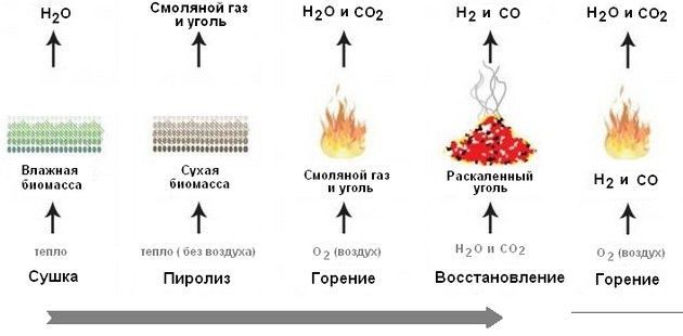
To be absolutely precise, the fuel does not burn “directly”, the gaseous products of pyrolysis burn. This means that before the firewood starts to burn , that is, it is oxidized by atmospheric oxygen with the release of heat, they must be heated to the temperature of evaporation of moisture in them, after which the process of evaporation of this moisture must go through, and only then the actual pyrolysis and combustion of pyrolysis gases will begin . Moreover, the processes of the first and second stages go with the absorption of heat, which is so necessary for the pyrolysis of the wood itself, without which there will be no combustion process itself.
My choice
 If, after reading, you no longer plan to heat with raw wood, then based on my life experience, I would recommend a pyrolysis boiler.
Prior to this, I already had two years of experience in operating the mine grate boiler KALVIS-2-70. Of the identified shortcomings, I note that its heat exchanger could not be cleaned from the resins deposited on it without preliminary heating to a temperature above 60 ° C. In the end, having realized all the technological flaws of this design, I decided to turn to specialists for its radical alteration. As a result of this deep modernization, I became the owner of a pyrolysis boiler.
Installation
It is better to place the boiler in a room specially designated for it, since I have not yet seen boilers that do not smoke in the room when reloading with fuel (and mine, moreover, sometimes smokes also due to design imperfections).
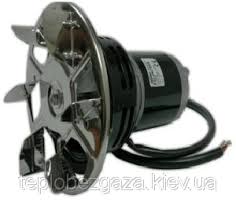
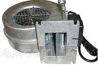
In addition, boilers are usually equipped with a smoke exhauster or a pressurization fan , which usually make quite a decent noise. The remaining control mechanisms for CO units (circulation pumps, air damper drives, chimney damper and ball valves with electric drives) operate almost silently.
Among other things, it must be taken into account that the boiler for its operation will require a large flow of air into the room in which it is located, which will cause cold drafts. Of all the above, the boiler is best located in a separate room in the body of the house.
My chimney is located vertically without bends and is part of the inner wall of the house, and during the operation of the boiler it additionally radiates heat into the house.
Since the boiler is a unit in which the generated heat is transferred to the coolant water, there are no “hot” parts on its surface, since it does not heat up above the boiling point of water. In addition, the water jacket on the outside is usually protected by a casing, the temperature of which rarely exceeds 30 – 35 degrees.
Firewood and more.
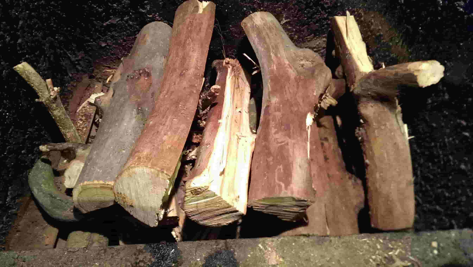
 The main fuel for the pyrolysis boiler is wood.
Any firewood is suitable: coniferous, deciduous, pine, oak, birch, etc. They all have approximately the same calorific value.. Hardwoods such as oak have a higher calorific value, but they are also more expensive, so I don’t see much point in chasing them. Any dead tree, fallen or dead wood is great for harvesting. The main thing is that the firewood is not raw and not expensive, it is better personally harvested, and it is more useful for the wallet and for health (you can easily save on a subscription to a fitness club). Partly because when buying on the side it is difficult to meet all the above conditions, I do not like to buy firewood. Somehow, in the first heating season, they brought me a car of firewood from the forestry, so their remains in the spring let out shoots and took root in my yard. Since then, I have been harvesting firewood only on my own.
In addition to firewood, the pyrolysis boiler is happy to consume straw, pellets, shavings, peat briquettes and ordinary peat, sorted household waste (paper, plastic, packaging, everything except PVC) and all this flavored with used oil or any other liquid hydrocarbon waste.
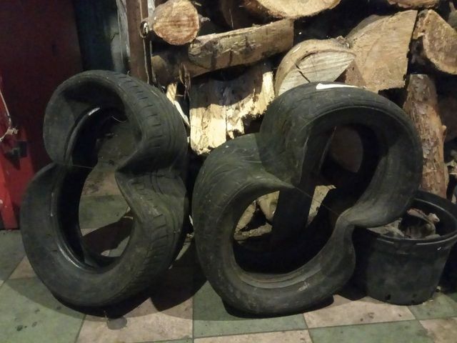
But the best fuel for the boiler can be a car tire. The calorific value of an automobile tire significantly exceeds the calorific value of the best wood species and is 32 GJ/t. Compared with it can, perhaps, the calorific value of high-quality coal. To all this, the tire has zero moisture, which is also a positive point. Well, if someone else has doubts that a tire can burn pretty decently, you can look at the gases coming out of my pipe and at the fire in the pyrolysis chamber.


The fact that not only I regard the tire as an excellent fuel can be judged by the number of
ads that offer the steel cord remaining after burning it.
The tire as a fuel is mentioned by me in this article only as a private successful experience, which became possible after a thorough modernization of a serial household boiler, subject to constant close monitoring of the combustion process through a video camera and operational control.
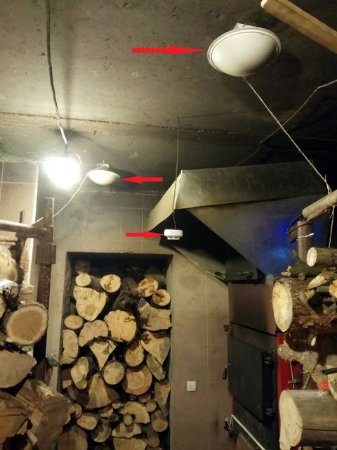
To ensure fire safety in the boiler room, I placed two Buran 2.5 automatic powder fire extinguishers and an autonomous smoke detector on its ceiling .
Ignition
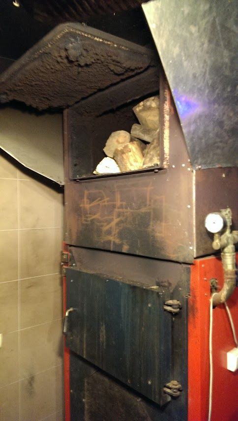 It is easier to fire up the boiler with a small amount of firewood (such a tab is carried out through the lower firewood loading window), but if desired, you can start the boiler with a full load (the upper firewood loading window is used for such loading).
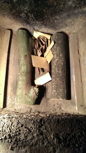
When starting with a full load, I ignite the boiler through the pyrolysis burner using a corrugated cardboard wick previously inserted into it (top view of the pyrolysis burner through the lower fuel loading window). A small amount of used engine oil and small wood chips also make lighting easier .
combustion products
The pyrolysis chamber of the boiler (aka the ash pan) has to be cleaned every time after the heating cycle (approximately 10-12 hours of continuous operation), since its volume is limited, and the pyrolysis gases still need to burn somewhere. 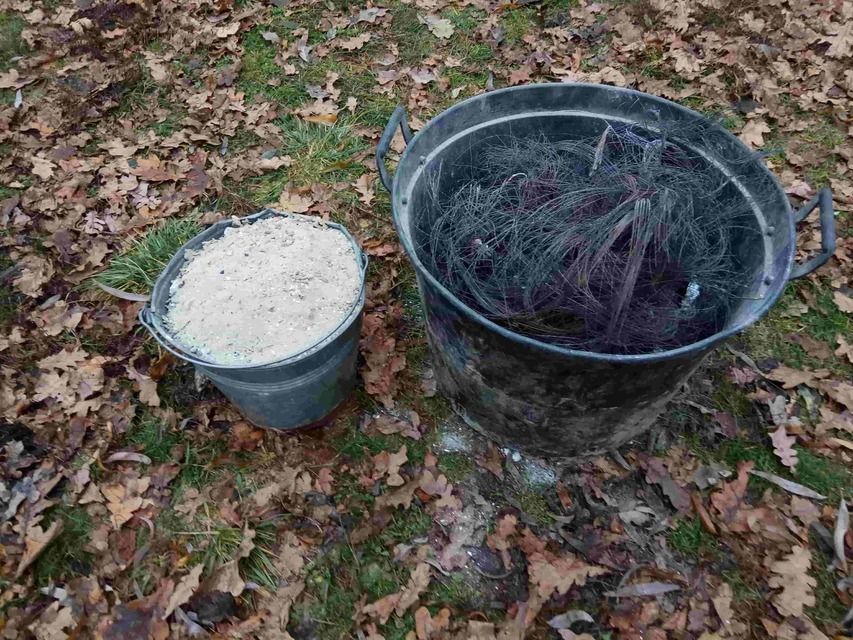 I try to clean the heat exchangers of the boiler through the heating cycle, that is, about twice a month, since the efficiency of the extraction of heat generated in the pyrolysis chamber depends on the degree of their purity. Usually, after one heating cycle, there is a bucket of ash and almost clean metal cord from the tires. Both ash and metal cord, as it turned out, are a valuable product for further use.
The products of complete combustion of TTK fuel are carbon dioxide, water and ash. That’s it water vapor and colors the smoke white on an unheated chimney. Soot can be a product of incomplete combustion of TTK fuel. A significant amount of it can color the smoke black, and a small amount, mixed with water vapor, in various shades of gray.
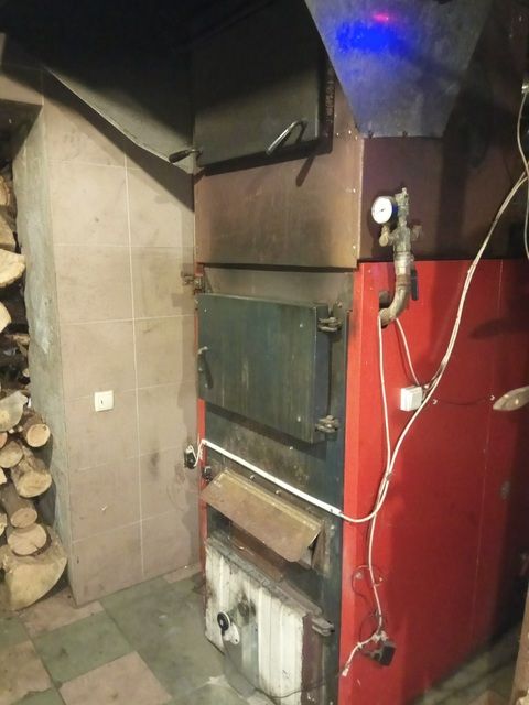
Boiler design

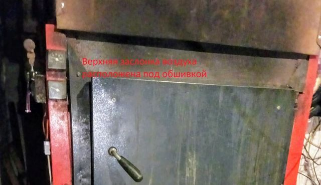
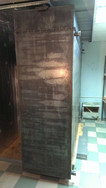
There are three doors on the front of my boiler:
- The top door is needed in order to increase the volume of a single load. The more firewood you can load at a time, the less often you have to do it.
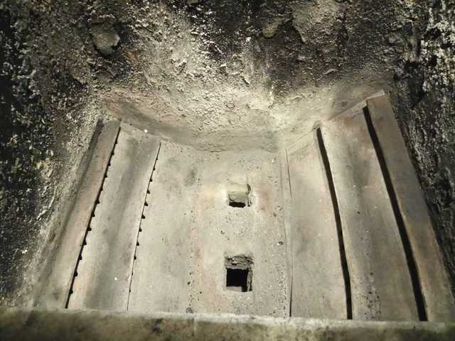
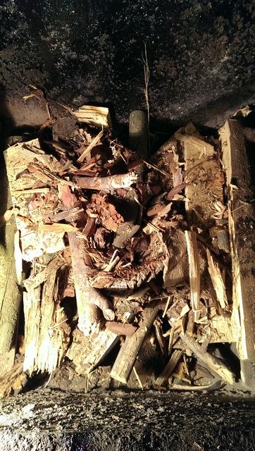
- The middle door is needed for boiler maintenance (ash removal, preparation for a new kindling), it is simply impossible to do this through the topmost door. Behind it is the loading chamber.Appearance of the loading chamber

- Behind the lower door is a combustion chamber for pyrolysis gases.Some details about the location of the combustion chamber

Air for fuel in my TTK is supplied through three air dampers to different zones of the boiler, which makes it possible to obtain the most efficient fuel combustion.
The presence of 3 air dampers, a temperature graph in the chimney and a video camera in the pyrolysis chamber allows minimizing heat losses and obtaining the most efficient combustion of not only various types of wood, but also more high-calorie fuels, such as sorted household waste and worn-out car tires.
My boiler, like most pyrolysis boilers, was born with one damper (now it is medium in height, it is also the main one). The damper is located on the front part of the boiler, below the lower fuel loading door.
Air is supplied through it to the fuel located above the burner and covers approximately 100 cm3 of firewood. This is the amount of fuel that is involved in the main combustion process. The same volume of fuel forms a coal cushion on which pyrolysis gases ignite .
The upper flap is located under the skin, above the lower fuel loading door. It appeared later, its task is to form an additional volume of pyrolysis gases, after the fuel located in the coverage area of u200bu200bthe middle damper has passed from the first to the third stages of pyrolysis, and no longer emits a sufficient amount of combustible gases in relation to the one supplied through it (mid flap) air volume.
The lower damper appeared last because of the need to supply additional air volume when burning more high-calorie fuel than firewood, for example, a car tire. The lower damper is located above the combustion chamber door and supplies additional air to the combustion chamber.
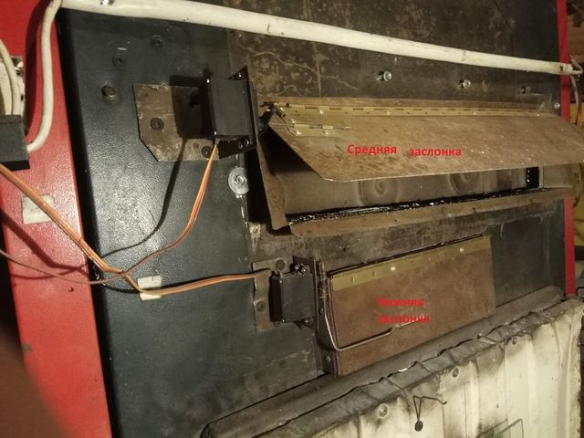
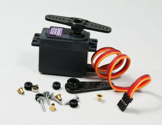
As drives for these dampers, inexpensive, but quite suitable for this purpose , MG996R 15kg servos are used .
Heating system
Usually, happy owners of the TTC go through the natural stages of evolution:
- The purchase of a boiler and the knowledge of the first joy from the warmth brought by it into the house. They feed him with small portions of firewood, feed him often and with pleasure.
- Then they try to stretch the time between feeding. Then they try to experiment with different types of food: they heat it exclusively with oak, acacia, and even coal, which is rare in our area.
- In the end, the understanding comes that “the cauldron exists for me”, and not “I am for the cauldron.”
- After that, the owner of the boiler begins to look for a place in the house for a heat accumulator (TA).
 I was more fortunate than the rest, even in the process of designing a house, I planned a place for myself under the TA, successfully passing this initial stage.
As a heat accumulator, you can use any container that can withstand the pressure in your CO (for me it does not exceed 1.5 kg / cm2), or make an indirect heating heater (the water circuit of such a heater exchanges heat with the boiler circuit through an additional heat exchanger), then it will be easier to fit into the space of the room. Here you can learn more about mine.
It should also be taken into account that the water temperature in the HE often reaches 94°C, so the material from which the HE is made and the pipe supplying the coolant to it must withstand these temperatures.
The heat accumulator does not have to be placed in the boiler room next to the TTK (even better outside of it), you can mount it in any room at home convenient for you ( you can even do that ).
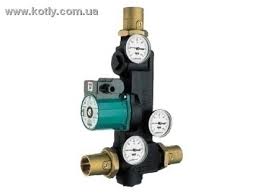
I also had to purchase Laddomat 21 , although it was quite possible to get by with a three-way mixing valve and a circulation pump for the boiler circuit.
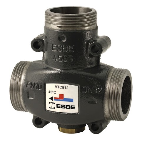
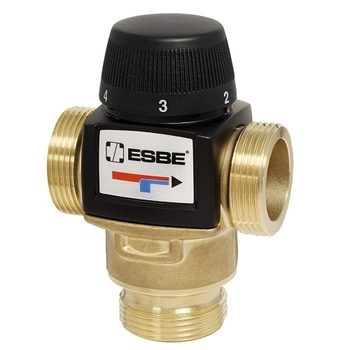
Thermostatic mixing valves were also needed for the underfloor heating circuit and the radiator circuit, although life later showed that radiators in CO with TTK and TA are meaningless.
It turned out to be useful in CO with TTK and an indirect heating boiler, well, and then on the little things: an expansion tank, a ball valve with an electric drive of the TA circuit, a boiler circuit and a boiler circuit. Circulation pumps for indirect heating boiler circuits, underfloor heating and radiators.

Automation
As the operation of its SO, the understanding gradually came that the system, in the form in which it was born, had significant flaws.
It turned out that for heating systems based on TTK + TA, it makes sense to comply with a number of conditions:
- It tends to send only surplus heat from the TTC to the TA.
- Cut off the TTC from the rest of the heating system (CO) after it stops generating heat, since after the fuel burns out, the TTC turns from the heat generator into its consumer and begins to suck out the previously stored heat from the HAT.
At first, it was necessary to manually connect the TTK to the CO during launch and also manually disconnect it from it. Manually divide the heat flows both at the beginning of the start-up of the TTC, and already during the operation of the boiler, when excess heat is formed. In addition, the standard air damper regulator was too inertial and could not cope with the tasks assigned to it.
And then it was decided to shift some of its simple boiler control functions to the fragile shoulders of automation. The use of an electronic control unit (CU) saved me from performing many routine operations. Also, along the way, the CU copes with such a trivial task as protecting the TTC from overheating, that is, it does what the vast majority of factory CU TT boilers do.
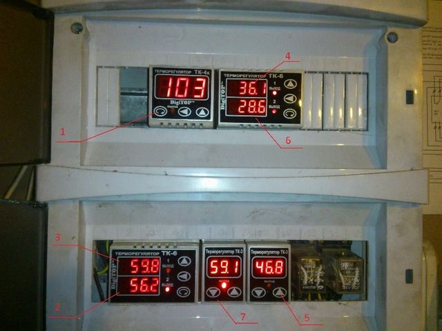
My first TTK control unit was far from perfect.
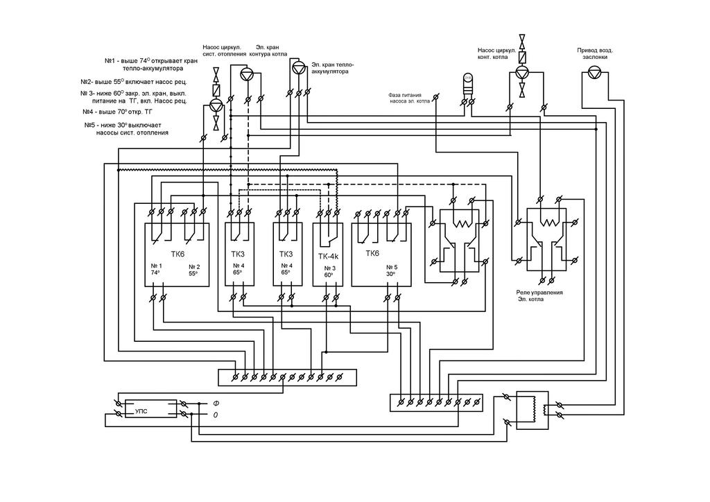
Every time I needed to correct or change the logic of CO work, my head swelled when I looked at this circuit and tried to understand how it works.
 In the end, with the participation of kind people, the CU acquired the form that it has today, as well as the much-needed functionality for me.
The screen graphically displays the current state of the main CO units that need to be monitored. At the same time, the screen is not overloaded with information, and it is easy to read.
Additional information about which equipment is currently used by the control unit can be obtained from the LEDs of the relay unit.
Circuitry
The control unit of my boiler is assembled on the basis of the Arduino Mega 2560 module. The choice fell on Arduino, because it is widely distributed, easily accessible, well documented, there are many lessons on its programming on the net, a huge friendly online community that will help, prompt, teach.
It is Arduino that allows you to realize the functionality of your device, limited only by your imagination. For example, your CU can control the TTK in winter, but it is enough to change the firmware in it and connect the connector of power devices to another group, and it will control the irrigation system of your backyard or, for example, a greenhouse. You can’t do such tricks with a factory BU TTK.

2. Arduino Ethernet Shield W5100
3. Graphic display QC12864B
4. 4-channel relay module – 2 pcs.
5. DC-DC converter step-down 4…38V to 1.25…32V to power the relay unit and display.
6. DC-DC converter step-down 4.5…28 V to 0.8…20 V 3A on MP1584 for a separate power supply of the “sandwich” Arduino Mega 2560 + Arduino Ethernet Shield W5100
7. Digital thermocouple amplifier MAX31855
8. THA thermocouple
9. Sensor temperature Dallas DS18B20 – 4 pcs.
10. TowerPro MG996R air damper actuator
11. Metal film resistor 4.7 kOhm
To power the control unit, a 12 volt battery is used, which in turn is connected to an inverter (600W). It also ensures the operability of CO circulation pumps.
Software
My boiler control unit is connected to a cloud service , this allows you to remotely monitor the state of the system, and, if necessary, also remotely make adjustments to the operation of the boiler and the heating system as a whole. Why ask for remote control of the heating system and, in particular, remote control of the operation of the TTC? I believe that only a very brave person can afford to leave a working boiler only under the supervision of a BU worth a little more than $ 100. I gained confidence in the need for remote control, as I gained my personal eight years of experience in operating the TTK.
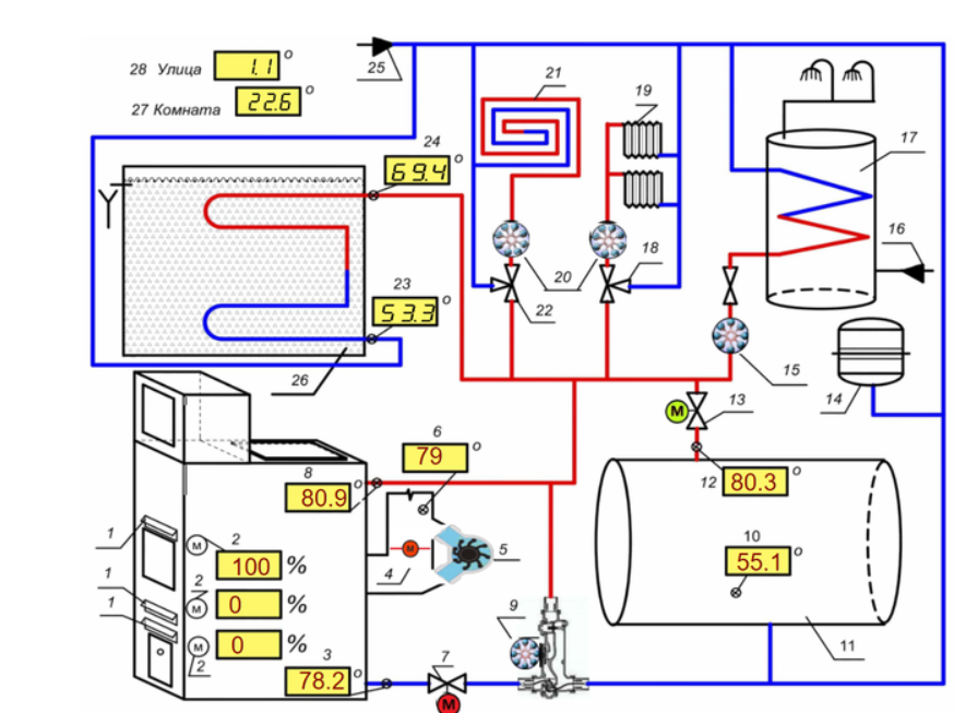
This serviceprovides an extremely useful possibility of graphical presentation of data from temperature sensors located at key points of the CO, which in turn gives an idea not only of the current static state of the CO, but also of the dynamics of the development of the processes occurring there. So, in particular, the data obtained from the “Graphics” tab give an idea of the current state of the CO, the correctness of the operation of its individual components in accordance with the program specified by the CU, and, unlike the data received from the CU monitor, give an idea of the dynamics of these data, the rate of change and direction of movement (growth or decrease), which is especially important at the time of threshold (critical) temperature values.
Whether the TTC was replenished with cold water from the HE or not, we can remotely, promptly track on the “Boiler input” graph, and whether this recharge had the expected result in protecting the boiler from overheating, we can track on the “Boiler output” graph. If the expected decrease in the water temperature at the inlet / outlet of the boiler did not occur, then for some reason the valve of the TA circuit did not open and the owner of the boiler needs to take adequate measures to protect the TTC.
Also, the data obtained from these graphs allow me to quickly notice and eliminate the boilermaker’s mistakes made when controlling the boiler.
In particular, thanks to the “Chimney stack” schedule, I noticed in time that I forgot to return the distribution damper to its working position, which directs the combustion products of the fuel bypassing the boiler heat exchanger into the chimney (usually it is transferred to this position when fuel is loaded to reduce smoke in the room), which in turn led to the flue temperature exceeding 250°C.


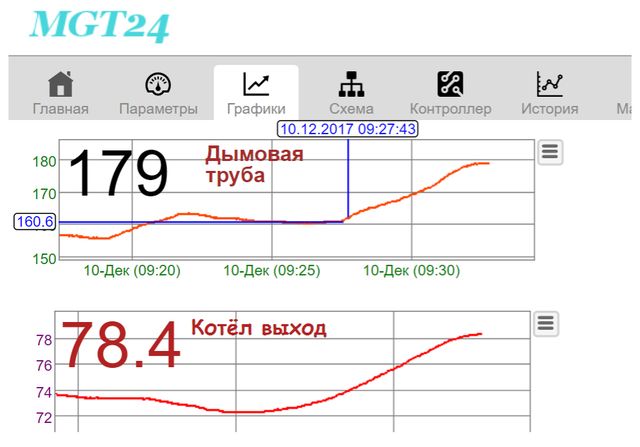
This part of the graph shows the beginning of the active stage of tire pyrolysis, which can be seen from the rapid increase in the temperature of the smoke and the temperature of the coolant at the outlet of the boiler, and as a result, an increase in the power of the boiler. At this moment, it is necessary to correct the position of the air dampers for the period of the active stage of tire pyrolysis.
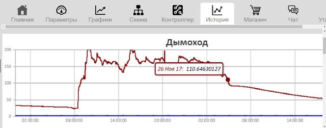
Looking at this graph, we can conclude that the duration of the boiler was approximately 20 hours and 30 minutes. After ignition, the boiler switched to active mode (smoke temperature over 110°C) after about 30 minutes of burning firewood. After another 30 minutes, the smoke temperature crossed the border of 135 ° C and the boiler switched to free draft mode (the control unit turned off the smoke exhauster and opened the chimney damper). Further, the boiler worked at its maximum power, until approximately 14:30 (at this time, most likely, the boiler was loaded with fuel).
In this mode, the boiler was completed until 5 a.m. the next day and when the temperature in the chimney dropped below 110 degrees. The TTK control unit put the boiler into sleep mode (turned off the circulation pump (“Laddomat 21”), No. 9, closed the ball valve of the boiler circuit No. 7, turned off the smoke exhauster No. 5, closed the smoke exhaust damper No. 4, opened the ball valve of the TA No. 13 circuit).
Further, the BU supplied the house with heat from the TA. I have only two TAs, each with a volume of approximately 4 m3. I discharged them one by one, the heat accumulated in them was enough for me for about five days.
Thus, the graphs in the “History” tab make it possible to analyze the operation of the entire system for the past periods and predict the next launch of the TTC in accordance with the needs of the residents of the house. In addition, such a view from the outside gives an understanding for further improvement of the heating system.
Conclusion
Sometimes people ask me why I chose wood heating? I answer, I was just lucky that I did not have a gas pipe nearby. Now I am a happy person, I don’t know how much “gas for the population” costs, I don’t take part in the discussion of heating tariffs, it just doesn’t bother me.
 Can a woman or teenager handle a solid fuel boiler? I think so, especially if there is no other alternative. After all, they managed somehow before, until the general “gas dependence” developed.
Cope and now in far from poor countries, for example, Germany or Spain.
By the way, I somehow, just in case (well, there the disease will overcome, or there will be frankly laziness) I also installed a 45 kW electric boiler in addition to the TTK, but in 6 years I turned it on only once when I checked it after installation.
My good friends, worrying about me, sometimes ask: “Isn’t all this fuss a burden to you? Have you ever wanted to drop everything and move to a place with central heating? So, not a burden, on the contrary, for me this is a very exciting activity for the realization of my creative needs. You see, I sing terribly, I dance badly, I don’t paint pictures at all, what else can you ask to brighten up the long winter evenings?
COMMENTS