1. Project Overview
The multi-component gas analyzer is one of the three main products recently developed by our company. With modular design, the configuration can be increased or decreased, and the components of oxygen, hydrogen, methane, propane and other gases in the mixed gas can be analyzed. Oxygen can use paramagnetic oxygen sensor and electrochemical oxygen sensor; hydrogen sensor can use thermal hydrogen sensor; carbon hydrogen sensor can use far-infrared gas sensor, which can detect methane and propane. The analysis of gas components requires fast response and stable operation, and the requirements for hardware are relatively high.
2. Hardware Design
In terms of hardware, fully consider the needs of system applications, AD acquisition, DA output, DI input, DO output and communication.
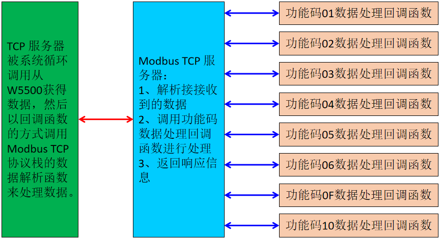
The communication part mainly includes serial communication and Ethernet communication. Ethernet communication adopts W5500 Ethernet controller and MCU to communicate through SPI bus. In this project, SPI2 is used to realize communication. The hardware design of Ethernet communication part is as follows:
There are two main objects of serial communication, far infrared hydrocarbon sensor and display screen. The far-infrared hydrocarbon sensor adopts single bus serial communication, TTL level. Two-way interface, usually one for use and one for standby, and two sensors can also be connected when needed, such as one for methane and one for propane. The design of the hardware interface is as follows:
RS485 or RS232 are used for the communication interface of the display screen. It is mainly for different application occasions. When a large display screen is required, the RS485 interface is selected, and the RS232 interface is used in the ordinary small display screen. But these two screens will not be used at the same time, so a USART port is used. The actual USART2 communication port is to use RS232 and RS485 to select different devices for welding. The design of the hardware part is shown in the following figure:
The analog input and output are completed by SPI interface and AD7705 and AD5663, and there are two analog input and output. The analog input is mainly used to collect hydrogen composition data and oxygen composition data. The hydrogen sensor uses the thermal principle to output a 0-5VDC signal. There are two types of oxygen sensors: paramagnetic sensor and electrochemical sensor. The paramagnetic sensor outputs a 4-20mA current signal, and the electrochemical sensor outputs a 0-2.5VDC signal. The two are not used at the same time, so the same AI channel is used. sensor soldering different devices. The hardware design is as follows:
There are also two analog outputs, which communicate with the MCU through the SPI bus. No way can output 0-5VDC signal. This part of the hardware design is relatively simple:
The digital input and output are mainly used for the control of small vacuum pumps and solenoid valves, as well as the input of buttons and status information. The hardware circuit is relatively simple:
There are other parts of the hardware design, which are relatively common and will not be discussed here.
3. Software debugging
The software development environment adopts IAR EWARM and STM32CubeMX. The basic configuration is completed in STM32CubeMX and the project is generated, and then the application is developed and debugged in IAR EWARM. The basic development and debugging will not be discussed, but the application development and debugging of digital input and output, analog input and output, serial communication and Ethernet communication will be discussed.
In order to make the software better adapt to the functional increase and decrease requirements of changing sensors and applications in different occasions, we used a configuration file when designing the software to configure more efficient use and increase or decrease. This configuration file is a header file that defines some macros to control conditional compilation. The selected part of the configuration file is as follows:
/*Multicomponent gas analyzer application version definition:
——0, for standard multi-component gas analyzer, version number VA1.0.1;
——1, for standard multi-component gas analyzer, version number VA1.0.1;
——2, for standard multi-component gas analyzer, version number VA1.0.1;
——3, for portable gas analyzer, version number V1.0.1B;
——4, B version application board, version number V1.0.1B; */
#ifndef MFC_MasterBoard_VERSION
#define MFC_MasterBoard_VERSION (0)
#endif
/* Define the enable of extended functions, only one item can be enabled at a time*/
//#define EXT_Ethernet_ENABLE //Extended Ethernet communication
//#define EXT_CAN_ENABLE //Extended CAN bus communication
/*Define on-chip Flash access enable*/
#ifndef STORAGE_ENABLE
#define STORAGE_ENABLE (1)
#endif
/*Global variable definition*/
#include “globalvariable.h”
/*Display control*/
#include “lcdcommunication.h”
/*Digital logic processing*/
#include “logicprocess.h”
/*Analog input and output processing*/
#include “addaprocess.h”
/*Ethernet communication processing*/
#include “ethernetprocess.h”
/* Infrared hydrocarbon sensor */
#include “ndirdataprocess.h”
/*On-chip Flash parameter access operation*/
#if STORAGE_ENABLE > (1)
#include “storeprocess.h”
#endif
/*Debug function*/
#include “CommonConfig.h”
The design and debugging of software in the aspects of analog input and output, serial communication and Ethernet communication have been less clear in the previous articles, only digital input and output are not involved, in the summary of this article We mainly talk about digital processing in software design and debugging. There are a total of 5 DI inputs and 5 DO outputs in the multicomponent gas composition analyzer. The GPIO configuration of these 10 pins is as follows:
/*Configure GPIO pins : DI1_Pin DI2_Pin DI3_Pin DI4_Pin
DI5_Pin */
GPIO_InitStruct.Pin = DI1_Pin|DI2_Pin|DI3_Pin|DI4_Pin
|DI5_Pin;
GPIO_InitStruct.Mode = GPIO_MODE_INPUT;
GPIO_InitStruct.Pull = GPIO_NOPULL;
HAL_GPIO_Init(GPIOE, &GPIO_InitStruct);
/*Configure GPIO pins : DO1_Pin DO2_Pin DO3_Pin DO4_Pin
DO5_Pin */
GPIO_InitStruct.Pin = DO1_Pin|DO2_Pin|DO3_Pin|DO4_Pin
|DO5_Pin;
GPIO_InitStruct.Mode = GPIO_MODE_OUTPUT_PP;
GPIO_InitStruct.Pull = GPIO_NOPULL;
GPIO_InitStruct.Speed = GPIO_SPEED_FREQ_LOW;
HAL_GPIO_Init(GPIOD, &GPIO_InitStruct);
/*Configure GPIO pin Output Level */
HAL_GPIO_WritePin(GPIOD, DO1_Pin|DO2_Pin|DO3_Pin|DO4_Pin
|DO5_Pin, GPIO_PIN_RESET);
For the operation of DI and DO, we use the definition operation function to realize the operation of a single channel and all channels. We first define two enumeration types as follows:
//Define the enumeration type of the digital output channel and specify the range of the channel
typedef enum {
DOChannel1,
DOChannel2,
DOChannel3,
DOChannel4,
DOChannel5,
DOChannelNum
} DigitalOutput;
//Define the enumeration type of the digital input channel and specify the range of the channel
typedef enum {
DIChannel1,
DIChannel2,
DIChannel3,
DIChannel4,
DIChannel5,
DIChannelNum
} DigitalInput;
The enumeration of digital input and output is mainly for the convenience of operation and identification. When the number of channels changes, it is only necessary to add two channel definitions for enumeration. There are 5 channels defined for digital input and output here. The last member of the enumerator represents the number of channels, which can avoid out-of-range errors when enumerating all channels.
At the same time, the following structure is also defined to define the GPIO target that needs to be operated.
//Define the target pin type for pin operation
typedef struct{
GPIO_TypeDef* GPIOx;
uint16_t GPIO_Pin;
}TargetPin;
With the above definitions, the operations envisaged above can be implemented. Next, we also need to define an array of TargetPin type of two digital input and output channels, which are used to store the target channels that we want to operate, and the two definitions of the previous enumeration. The channels are the same, and there are also 5 channels here.
//Define all target pin array of DI channel
TargetPin diPin[]={{GPIOE,GPIO_Pin_2},{GPIOE,GPIO_Pin_3},{GPIOE,GPIO_Pin_4}
,{GPIOE,GPIO_Pin_5},{GPIOE,GPIO_Pin_6}};
//Define the array of all target pins of the DO channel
TargetPin doPin[]={{GPIOD,GPIO_Pin_3},{GPIOD,GPIO_Pin_4},{GPIOD,GPIO_Pin_5}
,{GPIOD,GPIO_Pin_6},{GPIOD,GPIO_Pin_7}};
With the above two arrays, it is possible to avoid a large number of conditional branch statements (Switch or if statements) in the operation process, simplify the coding and avoid the need to modify the function when increasing the channel number. Now if the number of channels changes, it is only necessary to modify the values of the enumerators and arrays. Or if the pin of the operation changes, you only need to modify the value of the array. There is no need to modify the function body, and the coding of the function body is also very simple.
The operation of the digital output is as follows. When operating all channels, the enumeration variable is used as the loop variable, the last defined quantity of the enumeration is used to control, and the value of the enumeration is used as the subscript of the array, which effectively avoids the occurrence of overruns. The error of the range, and when the number of channels and the specific pins corresponding to the channels are changed, there is no need to modify the function.
//Operate all relay DO channels
//The input parameter TargetPin *doPin is the list of DO channels to be operated
//input parameter BOOL *commands list of values to be written to the DO channel
void OperationAllRelayChannel(TargetPin *doPin,BOOL *commands)
{
DigitalOutput DOChannel;
for(DOChannel=DOChannel1;DOChannel<DOChannelNum;DOChannel++)
{
OperationSingleRelayChannel(doPin[DOChannel],commands[DOChannel]);
}
}
//Operate a single relay DO channel
//The input parameter TargetPin doPin is the DO channel to be operated
//The input parameter BOOL command wants to write the value of the DO channel
void OperationSingleRelayChannel(TargetPin doPin,BOOL command)
{
HAL_GPIO_WritePin(doPin.GPIOx,doPin.GPIO_Pin,command);
}
The operation function of digital input is written in the same way as digital output. The reason why the enumeration can be used as an array subscript is because when the enumeration is not assigned a value, it always starts from 0 and accumulates upwards, which is exactly the same as the array subscript. Another advantage of this is that the channel and specific GPIO pins are determined by the assignment order of the TargetPin array, which is very convenient to modify.
//Get all DI quantity status input values
//The input parameter TargetPin *diPin is the list of DI channels to be read
//input parameter BOOL *result returns a list of read channel values
void GetAllDIStatusInput(TargetPin *diPin, BOOL *result)
{
DigitalInput DIChannel;
for(DIChannel=DIChannel1;DIChannel<DIChannelNum;DIChannel++)
{
result[DIChannel]=GetSingleDIStatusInput(diPin[DIChannel]);
}
}
//Get the state input value of a single DI quantity
//The input parameter TargetPin diPin needs to be read
COMMENTS