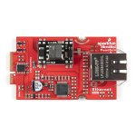
- WIZnet W5500 Ethernet Controller
- Hardwared TCP/IP embedded controller
- Supports TCP, UDP, IPv4, ICMP, ARP, IGMP and PPPoE protocols
- 32KB internal memory
- High Speed SPI support (80MHz clock speeds)
- Power conservation with Wake on LAN (over UDP) and Power Down modes
- Ag9900M Power-over-Ethernet (PoE) DC/DC converter
- Input Voltage Range: 36V to 57V
- Output Voltage: 5V
- 9 Watts Power
- IEEE802.3af compliant
- Configured for Alternate B (power on spare pair) power scheme
- RJ45 Connector with 10/100 Base-T Integrated Magnetics for PoE Applications
- Status LEDs for Ethernet Link and Activity
The W5500 Ethernet Controller from WIZnet is a TCP/IP embedded Ethernet controller that uses SPI communication protocol to allow up to eight independent sockets to operate simultaneously. The W5500 SPI interface operates at up to 80MHz and supports fast SPI for high speed Ethernet communication. The chip also includes a Wake on Lan (WOL) operation and power down mode to help conserve power.
The board uses a Ag9900m Power-over-Ethernet (PoE) DC/DC converter module to power MicroMod assemblies from a PoE source such as a router or network switch. The DC/DC converter supplies 9 Watts @5V to connected devices. This Function Board configures the PoE supply voltage to the IEEE802.3af Alternate B power scheme. This power scheme uses the spare pairs in the Ethernet cable (4,5 and 7,8) for positive and negative DC voltage, isolating power delivery from the data lines.
With the MicroMod standardization, users no longer need to cross-reference schematics with datasheets, while fumbling around with jumper wires. Simply, match up the function board’s M.2 edge connector to the slot of the M.2 connector on the main board and secure the function board with screws.


COMMENTS