In this tutorial, we go headlong into the Internet of Things (IoT)! We will teach you how to pass parameters to Arduino through your local network and still learn how to create two bedside fixtures, modeled and printed in 3D, controlled by Arduino + Ethernet Shield via the Android application.
Of course, the files are at the end of the tutorial for download! Then let’s go!
Overall scope of the project
This is an Internet of Things (IOT) project that brings together various technologies such as 3D modeling and printing, electronics, design, Arduino programming and AppInventor.
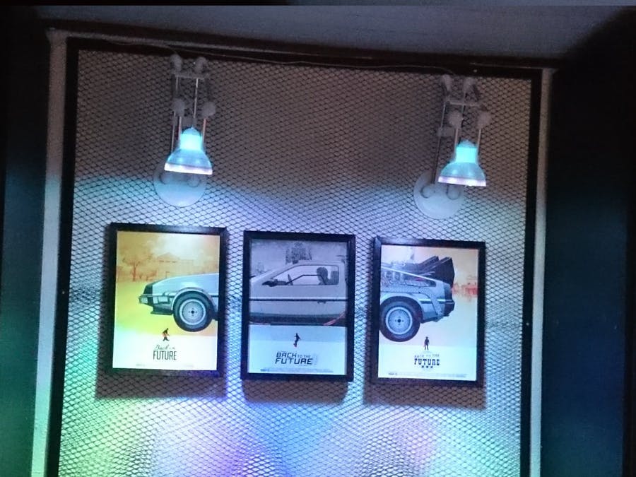
Basically we’re going to control two bedside fixtures. Each luminaire containing 15 RGB LEDs, thus being able to make the light of the luminaires take on any color we want.
We will pass the color parameters to Arduino through an Android application, so that it “converts” these parameters into colors in 8-bit RGB format.
All this in real time and within our WiFi network!
Below we have the simplified idea of our project:
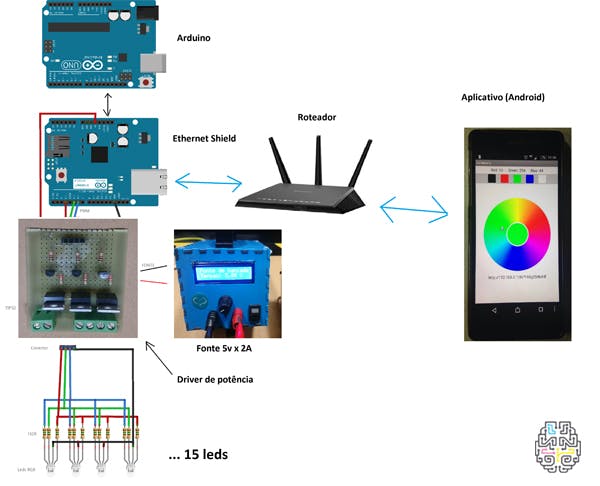
We’re going to need:
1st Arduino (Uno, Mega, Duemilanove)
1 Card drive (see text)
1 Ethernet Shield (W5100)
1 Wifi router
1 5V x 2A source
1st SmartPhone (Android)
30 Common Box RGB Leds
90 150 Ohms Resistors 1/8W
Modeling and Printing
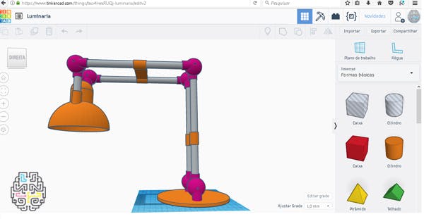
The project was initiated by modeling the domes of the luminaires.
To do all the modeling we use the TINKERCAD website , which is free and very easy to model simple parts. By having an intuitive interface, in a few minutes we can already create small and medium-sized parts.
Just “drag” a basic shape to the desktop and change according to the desired measures. You can also group basic shapes to form a composite part.
In addition to the printed parts, we use:
- Aluminum tubes of 13mm diameter to make the body of the luminaires
- 4 13x300mm aluminum tubes
- 2 13x100mm aluminum tubes
- 6 Screws M3 X 40mm
The characteristics of the printing can be seen in the table below:
Printer Anet A8 Fill 20% FILAMENT PLA Color Opaque White Printing temperature 210°C Printing time 9 hours each luminaire
Electronics
In addition to Arduino and Ethernet Shield, responsible for the communication and control of our luminaires, we manufacture a small circuit board to serve as a power drive for the 30 LEDs (15 of each luminaire).
The drive plate is responsible for receiving the Arduino signal and amplifying the power to power the 30 LEDs.
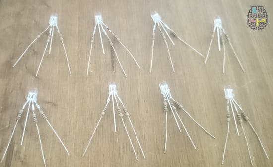
Remembering that RGB LEDs have 3 cores each. A red core, a green, and a blue. Therefore, our circuit is an X 3 power drive.
The LEDs are common method and each led core requires 1 resistor of 150 Ohms. And in the Catodo will not resist.
In the image, see the design of the power drive plate on the protoboard, the printed circuit layout, and the prototype made of standard (perforated) fiberglass board. And following the list of electronic components used.
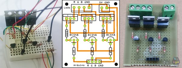
List of components:
1 Circuit board 3 Transistors TIP32 1 Female pin bar with 4 pins 3 Transistors BC548 3 Resistors 220 Ohms 1 KRE connector with 2-pin 3 Resistors 1 Kohms 1 KRE connector with 3 pins
Arduino Programming:
The code for Arduino is basically a pass of parameters via URL, arduino receives a “String” with a series of concatenated data and extracts the three PWM values. These values range from 0 to 255, 0 being the color erased and 255 color at maximum brightness.
EXAMPLE OF URL
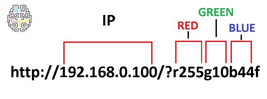
For each color a value (one value for red, one for green and one for blue) and with the combination of basic colors it is possible to make other colors, for example, orange, purple, pink, yellow, white, etc.
#include <SPI.h>
#include <Ethernet.h>
String leString;
char c;
String acao;
EthernetServer server(80);
int redPin   = 3; //PWM
int greenPin = 5; //PWM
int bluePin  = 6; //PWM
int R,G,B;
void setup() {
  byte mac[] = { 0xDE, 0xAD, 0xBE, 0xDA, 0xFE, 0xEE };
  byte ip[] = { 192, 168, 0, 100 };
  Ethernet.begin(mac, ip);
  server.begin();
  pinMode(redPin,   OUTPUT);
  pinMode(greenPin, OUTPUT);
  pinMode(bluePin,  OUTPUT);

  Serial.begin(9600);
  Serial.println("RED    GREEN    BLUE");
}
void loop() {
  //  exemplo de parâmetros  http://192.168.0.100/?R200G50B40f
  EthernetClient client = server.available();
  if (client) {
    while (client.connected()){
      if (client.available()){
        char c = client.read();
        if (leString.length() < 100) {
          leString += c;
        }

        if (c == 'n') {

          if (leString.indexOf("?") > 0) {
            int inicioR = leString.indexOf("r") + 1;
            int fimR    = leString.indexOf("g");
            acao = leString.substring(inicioR, fimR);
            R = acao.toInt();
            Serial.print(R);
            Serial.print("   ");
            int inicioG = leString.indexOf("g") + 1;
            int fimG    = leString.indexOf("b");
            acao = leString.substring(inicioG, fimG);
            G = acao.toInt();
            Serial.print(G);
            Serial.print("   ");
            int inicioB = leString.indexOf("b") + 1;
            int fimB    = leString.indexOf("f");
            acao = leString.substring(inicioB, fimB);
            B = acao.toInt();
            Serial.println(B);
            client.println("HTTP/1.1 200 OK");
            client.println("Content-Type: text/html");
            client.println();
            client.println("<HTML>");
            client.println("<HEAD>");
            client.println("</head>");
            client.println("<body>");
            client.println("RED = ");
            client.println(R);
            client.println("<p>");
            client.println("GREEN = ");
            client.println(G);
            client.println("<p>");
            client.println("BLUE = ");
            client.println(B);
            client.println("<p>");
            analogWrite(redPin  , R);
            analogWrite(greenPin, G);
            analogWrite(bluePin , B);
            client.println("</font><br>");
            client.println("</body>");
            client.println("</html>");
            client.flush();
            client.stop();
            leString = "";
          }
        }
      }
    }
  }
}  //fim do loop
Programming AppInventor:
The Android app was scheduled on appinventor 2.
A tool created by the Massachusetts Institute of Technology (MIT) that allows you to visually program (drag, drop, connect blocks of code) applications for devices with Android operating system.
The usability of the App is extremely simple, just tap the “color wheel” the desired color and the luminaire “magically” will copy is color! Woooohhhhooouuwww!!!
There are also buttons with preset colors for easy interaction.
In the final version of the App, an extra button was added to set up an IP other than the default (192.168.0.100).
So if this IP is being used on your local network, you can exchange it for another one and it will be stored in a small local “database” so that you do not need to reconfigure the IP with each use of the App. You can even set up a DDNS service and have control of your luminaires over the Internet from anywhere in the world.
Below, check out the video of printing, painting, assembly, testing and installation of our luminaires.
If you want to venture into the Internet of Things (IOT) start making your own luminaire, in the link of thingiverse Wall Lamp we prepare the files used in the project, and in this link are all arduino files + APK + Drive + Images for download. Good adventure!
See you next time!
Software analyst and developer, passionate about electronics and robotics, maker by nature and a DIY enthusiast. He has been working in electronics for 18 years, teaches courses in Schools and Universities of Arduino, Robotics, Electronics, 3D Printing and Internet of Things.
COMMENTS