I. INTRODUCTION
Nowadays home and building automation systems are used more and more, because they provide not only increased
comfort especially when employed in a private home but also allow centralized control of heating, ventilation, air
condition and lighting when employed in a commercial buildings. It is an emerging concept and lot of research has
been going on for more than a decade now in order to increase the power efficiency at the consumer level of the power
management systems. A residence that integrates technology and services through home networking to enhance power
efficiency and improve the quality of living is nothing but the Smart Home system [1, 2].Automation systems are plays
very important role in different areas, as shown in figure 1, like Office automation (refers to the varied computer
machinery and software used to digitally create, collect, store, manipulate, and relay office information), Building
automation (functionality to control the appliances of building), Power automation (control and monitoring of power
plants), and Home automation (automation of household appliances and features in residential dwellings).
This paper develops the home automation system, which is very useful to improve the lifestyle of the control of the
home devices in short. This type of automation Control system is combination of computer and information technology
to control the home appliance like telephones, TV outlets, electrical power, broadband wire, a doorbell and door lock.
This type of system provides energy efficiency, security and ease but also is made to reduce the manual worker [3].In
this paper introduction section provides the different automation system where as the section two i.e. literature survey
provides an overview on Smart Home Automation System developed in the recent year and section three provides the
Architecture and working of proposed system. Next Section provides the result and conclusion.
II. RELATED WORK
Rajeev Piyare and Seong Ro Lee [4] present a low cost and flexible home control as well as monitoring system. In this
system an embedded micro-web server is used for accessing and controlling devices and appliances remotely, using
Android based Smart phone app. The proposed system architecture is divided into three layers: home environment,
home gateway and remote environment. The proposed home automation system two types of software; one for server
application (it is a library implementation of a micro Web-server running on Arduino Uno using the Ethernet shield to
communicate between remote user and the Home Gateway) and other is for microcontroller firmware.
Basil Hamed [5] presents the hardware implementation of a multiplatform control system for house automation using
LabVIEW and consists of five parts; security systems (include fire alarm system and burglar alarm system), lighting
system (include the internal lighting of the house, and the ceil lighting outside the house), remote control system,
temperature system and fifth subsystem is Main house power switching system. All these five parts are connected to
LabVIEW software. This proposed system contains computer interfacing and remote control unit interfacing. Here
LabVIEW software is the main controller unit which receives data from house sensors, process information and updates
data for the difference systems, and transmit controlling signal to house systems and switching output devices.
III. PROPOSED SYSTEM AND ARCHITECTURE
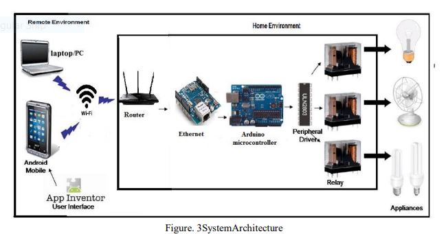
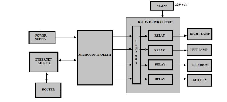
As the system uses Arduino, Ethernet are the main part of the project here the Ethernet shield acts as a server and
Ardunio microcontroller for programming. As per the Programming done in the Microcontroller, the Web page is
displayed on the screen in which the buttons are viewed as On/Off. When clicked on buttons (On), this feedback is
given to the microcontroller. There are 4 pins which are defined in the microcontroller i.e. pin 9, pin 10, pin 11, pin 12
are connected which are given to the 4 relays as shown in the setup figure 2 and 3 . Through Html language when the
on button is pressed, the data is passed into C language to the server. When clicked on button, pin 9 goes high (1)and
this goes to the ULN 2003 driver IC which converts the 5 volt from arduino to 12 volt which is given to the Relay.
Replay will operate, led will glow on and the device will operates and same process will continue same for pin 10,pin
11,pin 12. The communication used in Ethernet is SPI communication through Pins 10,11,12,13 are chip select
(CS),Master in slave out (MISO),Master in Slave in (MISI),serial clock (SCLK).
IV. EXPERIMENTAL RESULTS
The Microcontroller is programmed used HTML which is passed using ‘C’ language. Here a webpage has been created
to continuously monitored the home appliances through Wi-Fi and it enabled by w5100 Wi-Fi module. The first screen
that will be displayed to the user wherein the user has to establish connection with Wi-Fi network for remotely accessing appliances. Figure 2 shows the browser page which we designed using HTML language as a home page,
Once the home page is loaded, the user need to enter Ip address(192.168.0.110) to facilitate the further access to control
home appliances.
In the proposed system three devices are considered for demo purpose Light, bulb, mobile charger, fan on this page we
can control 4 devices just by clicking the menus on the web page, initially all devices Light, bulb, mobile charger will
be in off State i.e. ‘0’ state. The user can access this system using PC/Mobile.Using this GUI, user interacts with the
system to control devices. On successful establishment of connection, user can either operate devices (ON/OFF)
(energy consumed by each device) about devices.
When we click on button it will switched on the appliances and so on then we can switch off the appliance, here we
have taken bedroom as a part of example where it will control all the appliances which are present in the bedroom,
similarly for kitchen also.when’0′ state means the device will OFF when ‘1’ state means device will be ‘ON’.So in this
way we can turn on and off the appliances present in our homes.
V. CONCLUSION
In this paper the design and implementation of Smart Home Automation System (SHAS) that control home devices has
been established. The home automation using Ethernet shield has been experimentally proven to work satisfactorily by
connecting simple appliances to it and the appliances were successfully controlled remotely through Wi-Fi.
COMMENTS