introduction
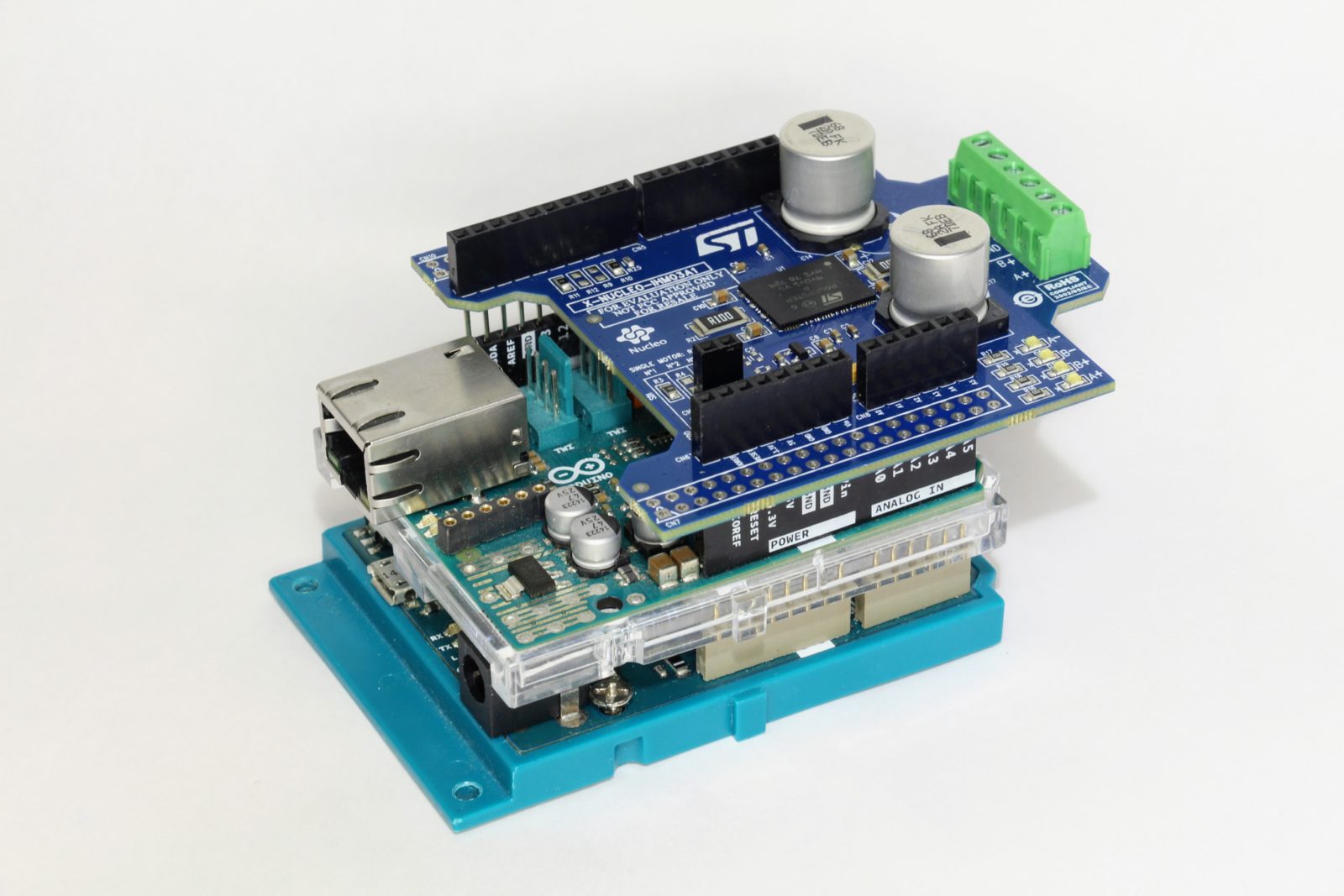
STEP100 (X-NUCLEO-IHM03A1)
Since some pins used by IHM03A1 and Ethernet Shield are overlapped so we need modify the IHM03A1 pin assignments.features
| Arduino | (Ethernet) | Default | Modified | Firmware | Note |
|---|---|---|---|---|---|
| D0 | |||||
| D1 | |||||
| D2 | FLAG | FLAG | Not in use | ||
| D3 | LED | Optional | |||
| D4 | SD CS | BUSY | SD CS | #1 | |
| D5 | |||||
| D6 | |||||
| D7 | |||||
| D8 | RST | RST | RST - PowerSTEP01 | ||
| D9 | STCK | STCK | Not in use | ||
| D10 | CS | CS | CS - W5500 | #2 | |
| D11 | MOSI | MOSI | MOSI - PowerSTEP01 | ||
| D12 | MISO | MISO | MISO - PowerSTEP01 | ||
| D13 | SCK | SCK | SCK - PowerSTEP01 | ||
| A0 | ID | ID | Not in use | ||
| A1 | |||||
| A2 | CS | CS - PowerSTEP01 | #2 | ||
| A3 | |||||
| A4 | |||||
| A5 | |||||
| MOSI | MOSI | MOSI - W5500 | SPI pin header | ||
| MISO | MISO | MISO - W5500 | SPI pin header | ||
| SCK | SCK | SCK - W5500 | SPI pin header |
1: SD CS and PowerSTEP01 BUSY
The D4 pin is used as the CS pin when reading the SD card on the Ethernet Shield, but it is also used as the BUSY pin on the IHM03A1. Unfortunately, the pins on both cannot be easily changed, so we are going to cut the legs on the IHM03A1. This pin indicates that the PowerSTEP01 is in BUSY state, but since the same information can be obtained via SPI, so there is no particular need to connect it to the Arduino. You can just cut it.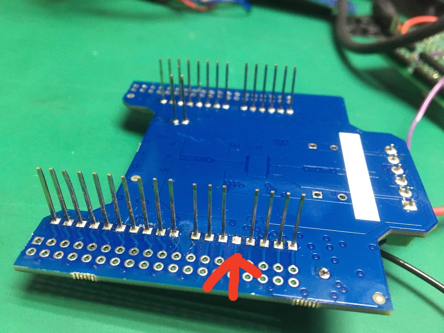
2: W5500 CS and PowerSTEP01 CS
The CS pin of the W5500 (or W5100) on the Ethernet Shield and the CS pin of the PowerSTEP01 on the IHM03A1 are both wired to D10, so change the IHM03A1 side. Remove the 0Ω resistor atR10 on the IHM03A1, then solder it to R9 pad. Now, the CS pin of PowerSTEP01 is changed from D10 to A2 pin.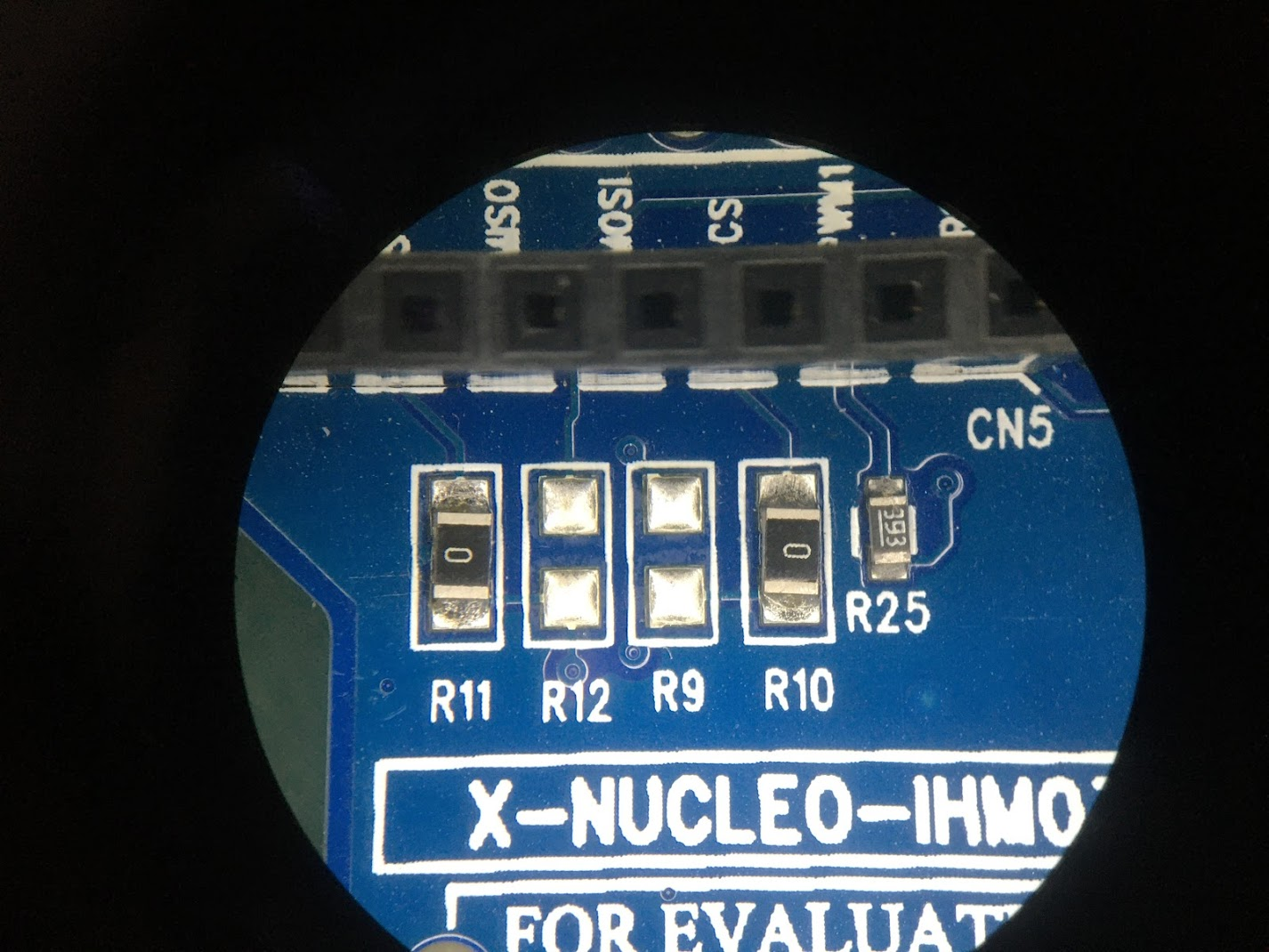 When removing the resistor, you need to heat the pads on both sides at the same time. Using two soldering irons is the easiest way to do this.
how to use
COMMENTS