MDK (Minimal Development Kit) – a baremetal ESP32/ESP32C3 SDK
A bare metal make-based SDK for the ESP32/ESP32C3 chips. Written from scratch using datasheets ( ESP32 C3 TRM, ESP32 TRM). It is completely independent from the ESP-IDF and does not use any ESP-IDF tools or files. The only requirement is GCC crosscompiler.
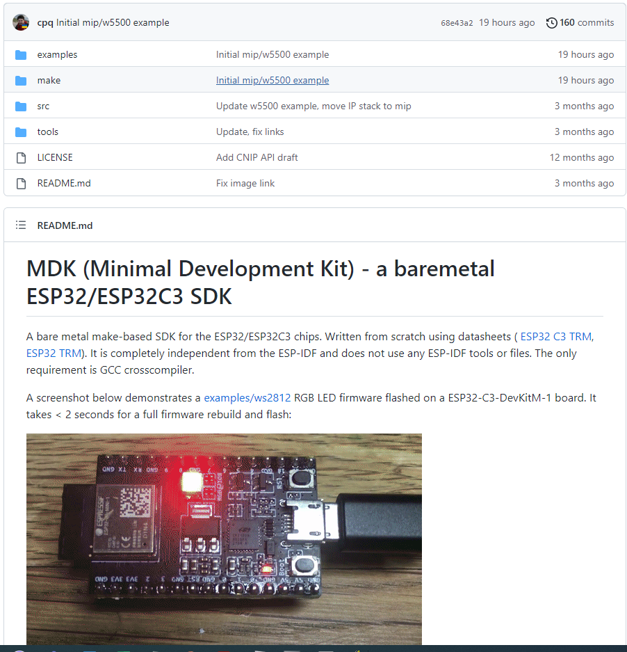
A screenshot below demonstrates a examples/ws2812 RGB LED firmware flashed on a ESP32-C3-DevKitM-1 board. It takes < 2 seconds for a full firmware rebuild and flash:
Environment setup
- Use Linux or MacOS. Install Docker
- Execute the following shell commands (or add them to your
~/.profile):
$ export MDK=/path/to/mdk                 # Points to MDK directory
$ export PORT=/dev/ttyUSB0                # Serial port for flashing
Verify setup by building and flashing a blinky example firmware. From repository root, execute:
$ make -C examples/blinky clean build flash monitorFirmware Makefile
Firmware Makefile should look like this:
SOURCES = main.c another_file.c

EXTRA_CFLAGS ?=
EXTRA_LINKFLAGS ?=

include $(MDK)/make/build.mk
Environment reference
- Environment / Makefile variables:
ARCH– Architecture. Possible values: esp32c3, esp32, posix. Default: esp32c3TOOLCHAIN– GCC binary prefix. Default: riscv64-unknown-elfPORT– Serial port for flashing. Default: /dev/ttyUSB0FLASH_PARAMS– Flash parameters, see below. Default: emptyFLASH_SPI– Flash SPI settings, see below. Default: emptyEXTRA_CFLAGS– Extra compiler flags. Default: emptyEXTRA_LINKFLAGS– Extra linker flags. Default: empty
- Makefile targets:
make clean– Clean up build artifactsmake build– Build firmware in a project’sbuild/directorymake flash– Flash firmware. Needs PORT variable setmake monitor– Run serial monitor. Needs PORT variable setmake unix– Build Mac/Linux executable firmware, see “UNIX mode” section below
- SDK Preprocessor definitions:
LED1– User LED pin. Default: 2BTN1– User button pin. Default: 9
API reference
API support matrix:
| Name | GPIO | SPI | I2C | UART | WiFi | Timer | System | RTOS |
|---|---|---|---|---|---|---|---|---|
| ESP32C3 | yes | yes | – | yes | – | yes | yes | – |
| ESP32 | yes | yes | – | – | – | yes | yes | – |
- GPIO src/ARCH/gpio.h
void gpio_output(int pin);              // Set pin mode to OUTPUT
void gpio_input(int pin);               // Set pin mode to INPUT
void gpio_write(int pin, bool value);   // Set pin to low (false) or high
void gpio_toggle(int pin);              // Toggle pin value
bool gpio_read(int pin);                // Read pin value
- SPI src/spi.h, src/spi.c
// SPI descriptor. Specifies pins for MISO, MOSI, CLK and chip select
struct spi { int miso, mosi, clk, cs[3]; };

bool spi_init(struct spi *spi);           // Init SPI
void spi_begin(struct spi *spi, int cs);  // Start SPI transaction
void spi_end(struct spi *spi, int cs);    // End SPI transaction
unsigned char spi_txn(struct spi *spi, unsigned char);   // Do SPI transaction
- UART src/uart.h, src/ARCH/uart.c
void uart_init(int no, int tx, int rx, int baud);   // Initialise UART
bool uart_read(int no, uint8_t *c);   // Read byte. Return true on success
void uart_write(int no, uint8_t c);   // Write byte. Block if FIFO is full
- SOC src/ARCH/soc.h
void wdt_disable(void);   // Disable watchdog
int sdk_ram_used(void);           // Return used RAM in bytes
int sdk_ram_free(void);           // Return free RAM in bytes
unsigned long time_us(void);      // Return uptime in microseconds
void delay_us(unsigned long us);  // Block for "us" microseconds
void delay_ms(unsigned long ms);  // Block for "ms" milliseconds
void spin(unsigned long count);   // Execute "count" no-op instructions
- Timer src/timer.h
struct timer {
  uint64_t period;       // Timer period in micros
  uint64_t expire;       // Expiration timestamp in micros
  void (*fn)(void *);    // Function to call
  void *arg;             // Function argument
  struct timer *next;    // Linkage
};

#define TIMER_ADD(head_, p_, fn_, arg_)
void timers_poll(struct timer *head, uint64_t now);
- Log src/log.h, src/log.c
void logf(const char *fmt, ...);   // Log message to UART 0
                                   // Supported specifiers:
                                   // %d, %x, %s, %p
void loghex(const void *buf, size_t len);  // Hexdump buffer
- TCP/IP
esputil
esputil is a command line tool for managing Espressif devices. It is a replacement of esptool.py. esputil is written in C, its source code is in tools/esputil.c. It works on Linux, UNIX and Windows. A pre-compiled Windows executable can be downloaded from the tools folder. Below is a quick reference:
$ esputil -h
Defaults: BAUD=115200, PORT=/dev/ttyUSB0
Usage:
  esputil [-v] [-b BAUD] [-p PORT] monitor
  esputil [-v] [-b BAUD] [-p PORT] info
  esputil [-v] [-b BAUD] [-p PORT] readmem ADDR SIZE
  esputil [-v] [-b BAUD] [-p PORT] readflash ADDR SIZE
  esputil [-v] [-b BAUD] [-p PORT] [-fp FLASH_PARAMS] [-fspi FLASH_SPI] flash OFFSET BINFILE ...
  esputil [-v] mkbin FIRMWARE.ELF FIRMWARE.BIN
  esputil mkhex ADDRESS1 BINFILE1 ADDRESS2 BINFILE2 ...
  esputil [-tmp TMP_DIR] unhex HEXFILE
Example: flash MDK-built ESP32C3 firmware:
$ esputil flash 0 ./build/firmware.binExample: flash ESP-IDF built firmware on ESP32-PICO-Kit board:
$ esputil -fspi 6,17,8,11,16 flash
  0x1000 build/bootloader/bootloader.bin
  0x8000 build/partitions.bin
  0xe000 build/ota_data_initial.bin
  0x10000 build/firmware.bin
Build esputil
Linux, macOS:
$ make -C tools esputilWindows:
Choose one of the below compilers, and use the provided command from the mdk root folder. Check to make sure the path points to where you installed the compiler.
Clang: (From PowerShell)
& 'C:Program FilesLLVMbinclang.exe' -v -o esputil.exe toolsesputil.cTCC: (From PowerShell)
& 'C:Program Filestcctcc.exe' -v -o esputil.exe toolsesputil.cMSVC: (From Developer Command Prompt)
cl toolsesputil.cESP32 flashing
Flashing ESP32 chips is done via UART. In order to do so, ESP32 should be rebooted in the flashing mode, by pulling IO0 low during boot. Then, a ROM bootloader uses SLIP framing for a simple serial protocol, which is described at https://docs.espressif.com/projects/esptool/en/latest/advanced-topics/serial-protocol.html.
Using that SLIP protocol, it is possible to write images to flash at any offset. That is what tools/esputil.c implements. The image should be of the following format:
- COMMON HEADER – 4 bytes, contains number of segments in the image and flash params
- ENTRY POINT ADDRESS – 4 bytes, the beginning of the image code
- EXTENDED HEADER – 16 bytes, contains chip ID and extra flash params
- One or more SEGMENTS, which are padded to 16 bytes
 | COMMON HEADER |  ENTRY  |           EXTENDED HEADER          | SEGM1 | ... |
 | 0xe9 N F1 F2  | X X X X | 0xee 0 0 0 C 0 V 0 0 0 0 0 0 0 0 1 |       | ... |

   0xe9 - Espressif image magic number. All images must start with 0xe9
   N    - a number of segments in the image
   F1  - flash mode. 0: QIO, 1: QOUT, 2: DIO, 3: DOUT
   F2  - flash size (high 4 bits) and flash frequency (low 4 bits):
            size: 0: 1MB, 0x10: 2MB, 0x20: 4MB, 0x30: 8MB, 0x40: 16MB
            freq: 0: 40m, 1: 26m, 2: 20m, 0xf: 80m
   ENTRY - 4-byte entry point address in little endian
   C     - Chip ID. 0: ESP32, 5: ESP32C3
   V     - Chip revision
Flash parameters
Image header format includes two bytes, F1 and F2, which desribe SPI flash parameters that ROM bootloader uses to load the rest of the firmware. Those two bytes encode three parameters:
- Flash mode (F1 byte – can be
0,1,2,3) - FLash size (hight 4 bits of F2 byte – can be
0,1,2,3,4) - Flash frequency (low 4 bits of F2 byte – can be
0,1,2,f)
By default, esputil fetches flash params F1 and F2 from the existing bootloader by reading first 4 bytes of the bootloader from flash. It is possible to manually set flash params via the -fp flag, which is an integer value that represent 3 hex nimbles. For example fp 0x22f sets flash to DIO, 4MB, 80MHz:
$ esputil -fp 0x22f flash 0 build/firmware.binFLash SPI pin settings
Some boards fail to talk to flash: when you attempt to esputil flash them, they’ll time out with the flash_begin/erase failed, for example trying to flash a bootloader on a ESP32-PICO-D4-Kit:
$ esputil flash 4096 build/bootloader/bootloader.bin
Error: can't read bootloader @ addr 0x1000
Erasing 24736 bytes @ 0x1000
flash_begin/erase failed
This is because ROM bootloader on such boards have wrong SPI pins settings. Espressif’s esptool.py alleviates that by uploading its own piece of software into ESP32 RAM, which does the right thing. esputil uses ROM bootloader, and in order to fix an issue, a -fspi FLASH_PARAMS parameter can be set which manually sets flash SPI pins. The format of the FLASH_PARAMS is five comma-separated integers for CLK,Q,D,HD,CS pins.
A previously failed ESP32-PICO-D4-Kit example can be fixed by passing a correct SPI pin settings:
$ esputil -fspi 6,17,8,11,16 flash 4096 build/bootloader/bootloader.bin
Written build/bootloader/bootloader.bin, 24736 bytes @ 0x1000
COMMENTS