This project describes the construction of an NTP (Network Time Protocol) Stratum-1 Time Server using a GPS source and an Arduino Mega 2560 microcontroller. The description here is based significantly on the initial work of Russell and Jon Slater who constructed the first unit for use at the South Downs Planetarium.
The server can be accessed by any client computer running NTP software to synchronise the computer’s internal clock to the GPS time reference. It can be connected either directly or via a LAN. It is particularly suited to situations where an accurate UTC time reference is required for computers that are isolated from the internet.


The hardware
Hardware changes are needed for this particular combination of Arduino boards (known as shields) and will vary with the versions of board purchased. Four examples of this Time Server have been built over a period of 18 months using different board versions and photos from both are shown to illustrate the differences that typically occur and need to be understood if a satisfactory end result is to be achieved. The basic parts list is as below, with details following:
- Arduino MEGA 256A R3 Development Board
- Arduino Ethernet Shield W5100
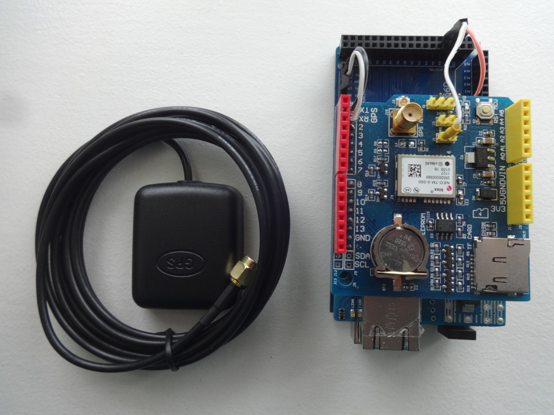
- GPS Shield for Arduino, with separate active antenna
- Wire links, connecting cables, +5V psu (optional), box and mounting fixings all as described in the text
Arduino MEGA 2560 R3 Development Board

Arduino Ethernet Shield W5100


GPS Shield for Arduino


The board must have a 1 PPS (sometimes simply ‘PPS’,) signal available on a solderable pad. A separate active antenna is also recommended to ensure a strong GPS signal, especially for use inside buildings where reception is poor. Some boards have a holder for a Lithium ion button battery (CR1220) which enables satellite data to be stored after the first fix, making subsequent time to fix on power-up much quicker.
Other equipment needed
A USB A to B ‘printer style’ cable for programming the Arduino Mega, which also provides 5V power to the assembly. ln use, an alternative is to provide 5v 0.5A from a small regulated PSU via a 2.1mm coaxial connector on the Mega.
Ethernet {CAT 5/6/7) cable (or ‘crossover’ cable, see text), as required’ Note that this can be a significant length if it enables the NTP server to be located remotely from the target PC in a better GPS signal area. A few short lengths of signal wire and pins for the additional interconnections needed, plus the ability to solder the links and jumper wires.
Modifications
The following links are needed:
- Ethernet INT to Mega pin 48
- GPS PPS to Mega pin 49
- GPS Tx pin 0 to Mega pin 19
- GPS Rx pin 1 to Mega pin 18
The Ethernet card raises an interrupt that the Arduino Mega uses as a time reference marker within the NTP message-handling protocol. That interrupt is available on the board on a solder pad close to edge connector pin 2 (conveniently, but not always, labelled as INT on some board versions) and a jump lead needs to be soldered to the pad to connect it to the Mega.

PPS marks the edge of the precise second transition from the GPS and is used here as an interrupt to enable UTC to be determined to an accuracy of a few microseconds within the server.
GPS Tx and Rx cannot use the same pins as the Ethernet Tx/Rx when the boards are stacked, so must be isolated from edge connector pins 0 and 1. Some board versions enable this to be easily achieved by a system of manual links. Others will need the edge connector pins to be unsoldered or snipped off to achieve isolation from the board below, with the required links then soldered to the vacant pin pads.
Some boards may have a 3.3V/5V selection switch for the power source used. Select 5V.
Method
The three boards are stacked with the Arduino Mega on the bottom, Ethernet shield in the middle and GPS shield on the top. Ensure that the 6-pin connector on the underside of the Ethernet board correctly locates to the mating connector on the Arduino Mega. Connect the flying links from the stack to the Mega as detailed above. Connect the active antenna. Connect the USB cable to provide power to the stack. Use a ‘crossover’ Ethernet cable to connect the server directly to the client PC or use conventional 1:1 patch cables to connect via a router or Ethernet switch. Upload the Arduino software. Download NTP software from Dimension 4 onto the client PC.
The software
Arduino software
Software for the Arduino Mega can be found at: https://github.com/jonsl/arduino-ntpd/
Those with no previous experience of uploading software to Arduino microcontrollers are referred to https://www.arduino.cc/en/Guide/HomePage
The following steps are needed:
Download the Arduino desktop IDE (Integrated Development Environment) software (e.g. Arduino 1.8.5) Download the Arduino software from the Github source. Verify and upload the software onto the Mega using the USB cable.
Client PC NTP software
Suitable software is available free to download from Dimension 4 http://www.thinkman.com/dimension4/
Download the Dimension 4 software to the client PC. To set the IP address of the Time Server, select ‘settings’ then type 192.168.1.251in the Server window and ‘Arduino’ in the Location window. Select OK. Under ‘Advanced’ check that ‘Use the selected server’ is selected. Under ‘How often’ on the front page set the update rate as required (e.g. every 15 minutes).
If the Time Server is to be used in a network controlled by an ADSL router, then the router will allocate any further IP address requirement. If, however, the Time Server is to be connected directly to a PC or indirectly to a PC via a dumb Ethernet switch, then the PC will need to have a fixed IP address for Ethernet communication. Typically for a Windows10 machine, select ‘Settings/Network & Internet/Ethernet/Properties/Internet Protocol Version 4 (TCP/IPv4)/Properties’ then select ‘Use the following IP address’ and enter 192.168.1.252 in the window.
Connect the Arduino time reference, power it up and allow time for the GPS module to find and sync to satellites, sometimes noted when an LED on the board starts to flash at a rate of 1Hz. The Dimension 4 software should acknowledge it is ‘seeing’ the server and will return a time correction.
Mounting arrangements
A suggested mounting arrangement is as below, using a simple ABS project box with the board stack mounted on short M3 pillars and the connectors accessible through the box wall.


Software Installation Guide
- Download arduino ide: https://www.arduino.cc/en/Main/Donate Press ‘Just Download’ at the bottom of the screen;
- Run the downloaded installer (in this case arduino-1.8.5-windows.exe) and press ‘I Agree’->’Next’->’Next’;
- When the installer asks to install device software click ‘Install’ each time;
- Double click the installed arduino ide on the desktop, and check ‘Private networks, such as my home or work network’ and click ‘Allow access’;
- Go to: https://github.com/jonsl/arduino-ntpd click ‘Clone or Download’->’Download Zip’;
- Make a new folder in your Documents directory called ‘dev’, and copy the downloaded ‘arduino-ntpd-master.zip’ into it, and unzip it in place;
- In the ‘Documentsdevarduino-ntpd-masterarduino-ntpd’ folder, double click the file ‘arduino-ntpd.ino’;
- When the ide has started, go to ‘Tools’->’Arduino/Genuino Uno’-> and select ‘Arduino/Genuino Uno Mega or Mega 2650’;
- Make sure ‘Processor’ is set to ‘ATmega2560 (Mega 2560)’;
- Go to port and make a list of all the COM ports there – then close the whole Arduino ide;
- Plug in the arduino board that you will program into the computer via USB and start the Arduino ide again;
- go to ‘Port’-> and select the COM port that is now present, that was not present before (in the list you made in 10.);
- Go to ‘Sketch’->’Include Library’->’Add .ZIP Library’ select the file ‘Documentsdevarduino-ntpdarduino-ntpdlibrariesTinyGPS.zip’ and click ‘Open’;
- Click the green tick mark (top left) to verify the library builds, you should see something like the following:
Sketch uses 23392 bytes (9%) of program storage space. Maximum is 253952 bytes.
Global variables use 2901 bytes (35%) of dynamic memory, leaving 5291 bytes for local variables. Maximum is 8192 bytes.
- Click the green right arrow next to the (tick mark) to upload the library to the board.
If the upload fails, simply unplug the board from the USB socket, plug it back in again and then press the green right arrow again.
COMMENTS