introduction
This circuit board is to be used for heating control and as a timer. The temperatures are measured with Dallas thermometers. The time information is taken over by the transmitter DCF77. 16 relay drivers are available as switching outputs. Additional switching outputs can be added with 230V wireless sockets. The ferbe control transmitter is controlled via an I/O pin.The control system is operated and adjusted via the Ethernet interface. Only one device with an HTML browser is required for operation.The controller is also programmed via the Ethernet interface with the TFTP protocol. The initial programming of the bootloader can be done with the ISP interface on the PCB (without WIZ810MJ). Software updates can then be installed via the Ethernet interface.This allows the controller to be placed close to the heating (or e.B the underfloor heating distribution). From there, a TP line leads to the house switch.
features
Hardware
Features
- Ethernet interface with WIZ810MJ module
- Atmel Controller with DIL28 Package ATmega8, 48, 88, 168
- Atmel Controller with DIL40 Package ATmega16, 32 644
- 16 relay drivers, for controlling 24V relays (limited to 8 relays with DIL28 MCU)
- Connection of a DCF77 receiver via current interface
- 1-wire-bus controlled with MCU port pin
- 1-wire-bus with active driver for long lines (DIL40 MCU only)
- Connection for 433 MHz remote control transmitter
- one input line (only with DIL40 MCU)
- Serial interface, RxD and TxD
- additional status LED for Collision Detect, Rx activity, Tx activity and Link Speed
- ISP interface for programming the controller for the first time (only possible without WIZ810MJ)
- PCB for slide-in housing
- small dimensions (60 mm by 97 mm)
- All components for through-hole mounting (THT)
- All connections on one side of the PCB
- Important connections (16 relay drivers, power supply, 1-wire bus, DCF77, input line) on one connector
- optional 2. Power supply connectors
- Different power supply variants possible
- a. MCU with 5V and WIZ810MJ with 3.3V for maximum MCU clock
- b. 6V - 9V operation with 7805
- c. for input voltage >9V use of an integrated switching regulator
- d. MCU and WIZ810MJ powered by 3.3V switching regulator
technical details
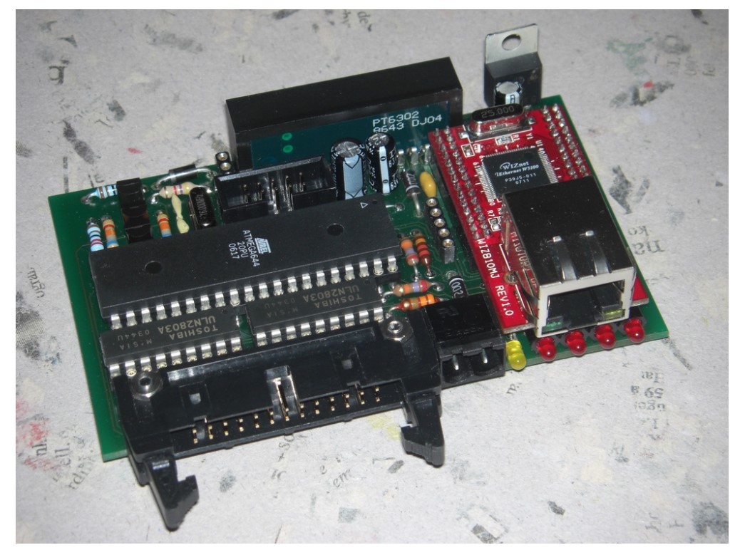
View of the PCB equipped with ATmega644

Assembly plan

Assembly plan of the printed circuit board
Schematic

Schematic
Software
Only the TFTP boot loader is currently available as software.Downloads
The competition entry can be downloaded here: http://www.circuitcellar.com/wiznet/winners/DE/001179.htmlhow to use
COMMENTS