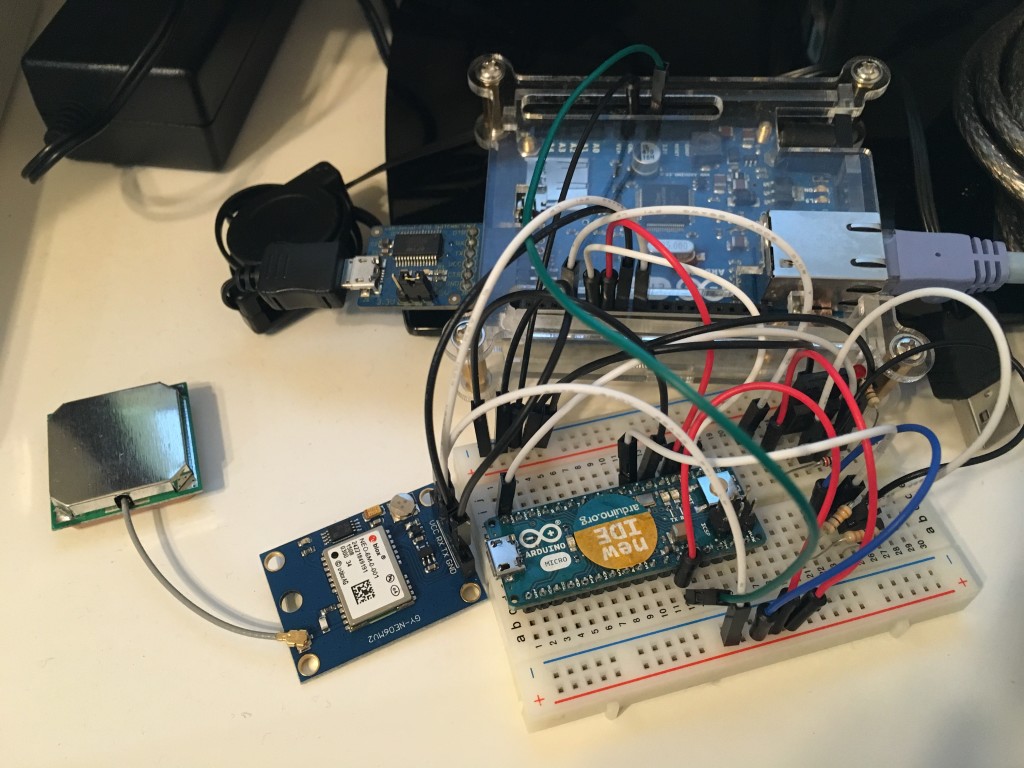

It is possible to read, and log GPS data, such as time, position, speed, and so on, using an Arduino microcontroller plus an U-blox NEO-6M GPS receiver.
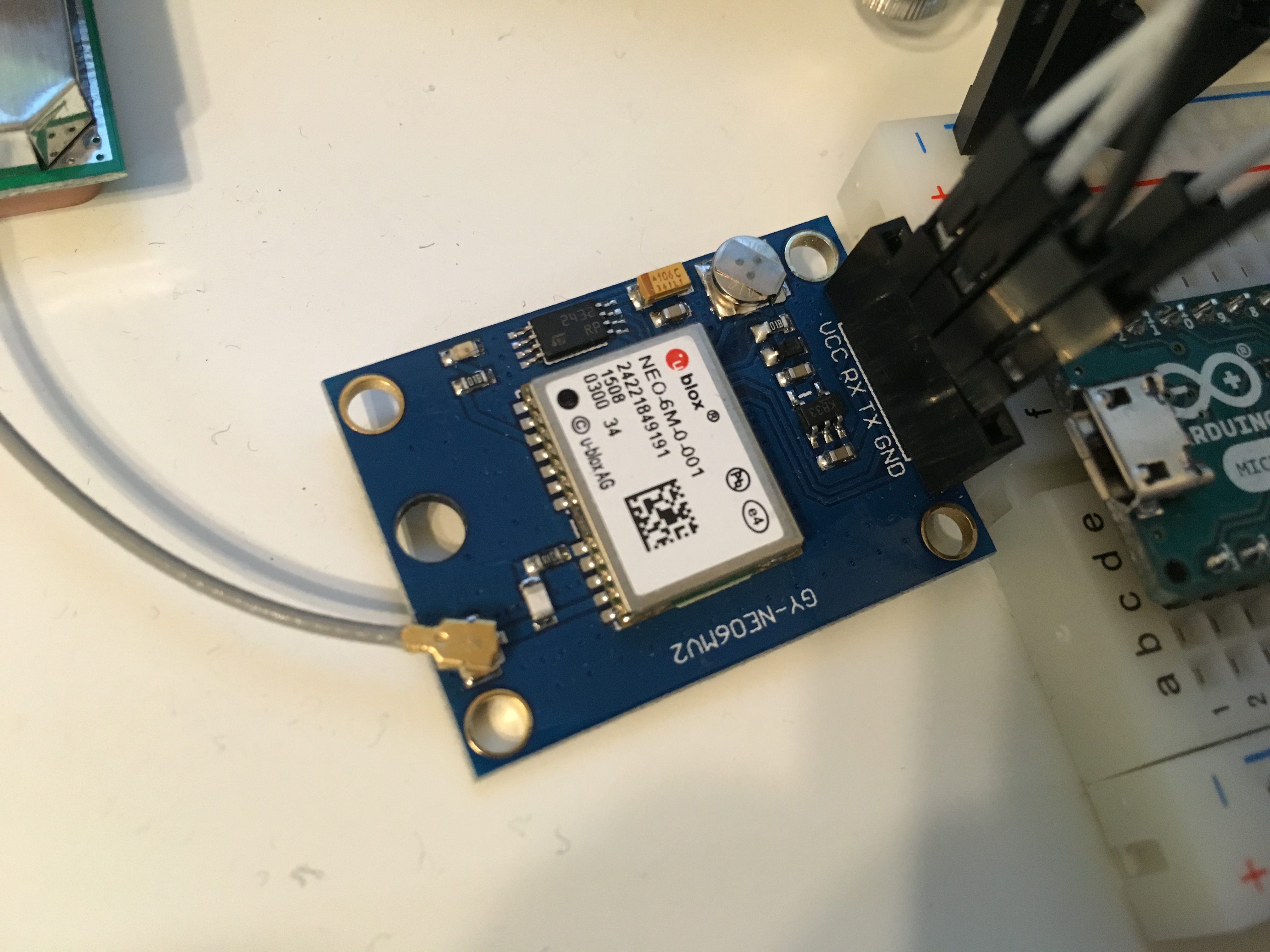
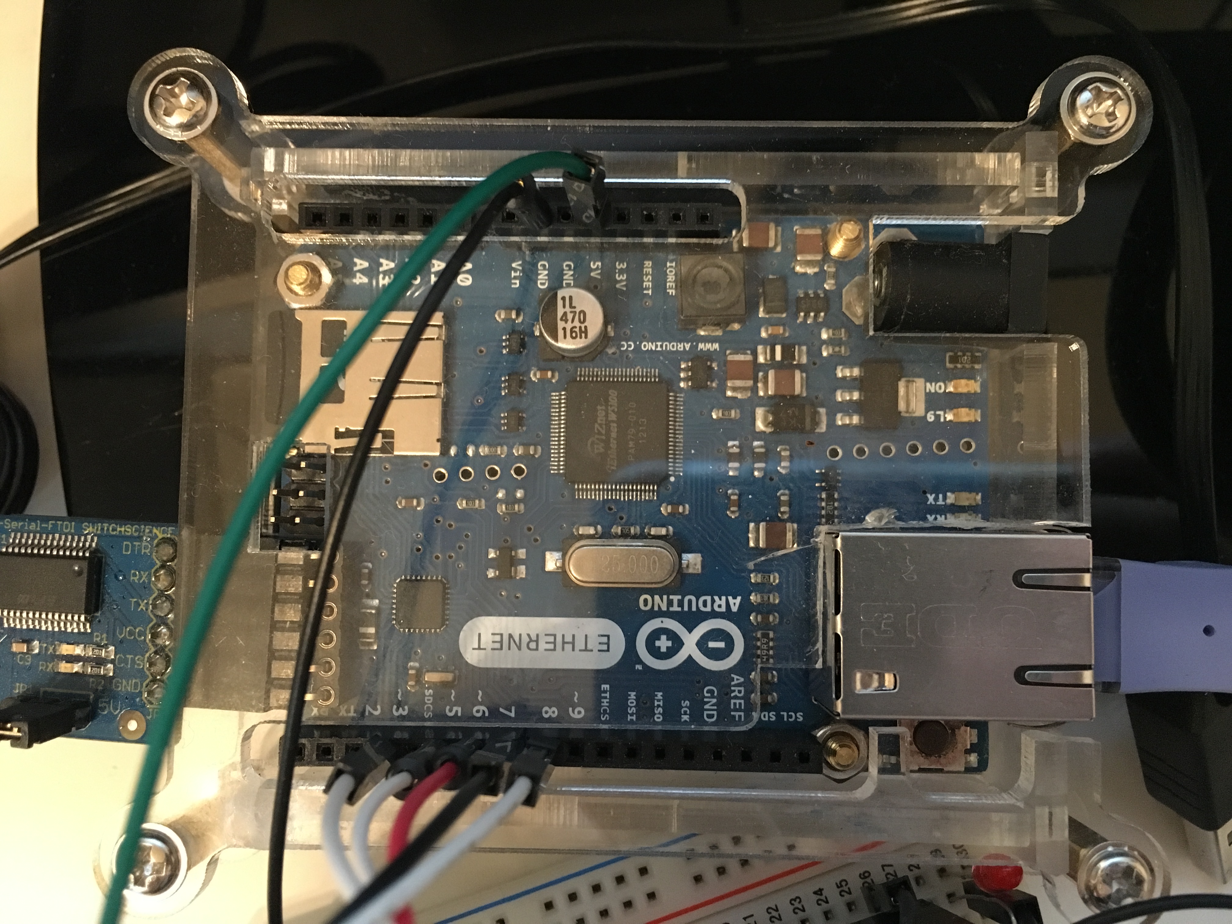
For my test, I used an Arduino Ethernet and a U-blox NEO-6M GPS, which I bought on Amazon Japan for 2,580Yen (about 17 Euro), a very cheap price.
In order to interface the Arduino with the GPS receiver, you have to connect the following pins: power supply VCC (5V), GND (0V), and serial RX and TX. You need to connect the GPS receiver TX to the Arduino RX, and RX with TX. Actually, the NEO-6M GPS serial communication works with 3.3V voltage signal, while Arduino works with 5V voltage signals. However, it is possible to connect the Arduino serial pins directly to the NEO-6M pins without any problem.
On Arduino side, I used the pins 7 (RX) and 8 (TX) and the Software Serial Library. In fact, the Arduino built-in serial port (0=RX, 1=TX) was already used for the communication with the PC. In the picture below, pins 3, 5 and 6 are also connected to an other Arduino Micro, but these pins are not used in this sketch.
The following Arduino sketch is continuously polling, once in a second, data from the GPS receiver. In order to poll GPS data, the command PUBX,00 is used (this is a proprietary command of U-blox). The received data is then forwarded to the PC serial connection, and visualized on the screen.

I removed part of the information, for privacy (otherwise you would know exactly the coordinates of the place where I live). The message forwarded to the PC is as below (instead of “xxxx” and “yyyy”, the latitude, longitude and height positions were received). The original message received by the GPS receiver has a “$” at the beginning, and a “*” at the end (before the checksum). I used these 2 character to understand when the message starts and when it ends. The data which Arduino sends to the PC is only the characters between “$” and “*” (I did not implement any checksum check at the moment).
PUBX,00,131309.00,aaaaa.bbbbb,N,ccccc.ddddd,E,xxx.yyy,G3,28,22,1.757,8.60,0.032,,1.86,2.76,1.99,6,0,0
The sketch that I used is as following, and can be downloaded here: GPS_serial_test. In order to run this sketch, you will also need the “Tempo” library which uses Timer1 and can be downloaded here: tempo_library_v1. I used Timer1 in to create a 10ms scheduler, and manage the polling request every 100 scheduler tasks (10ms x 100 = 1s).
By default, the NEO-6M outputs RMC, VTG, CGA, GSA, GSV, GLL messages once a second (these are standard NMEA messages). Since I wanted to receive the info by polling message (i.e. not automatically, to avoid Arduino sofware serial reception overloading), I first had to disable the automatic sending of the messages (for example, for RMC, this can be done by sending to the GPS receiver the command: $PUBX,40,RMC,0,0,0,0*47). This configuration is performed at the first loop execution. The software then polls the info (time, position, speed) by using the proprietary $PUBX,00*33 request.
1 2 3 4 5 6 7 8 9 10 11 12 13 14 15 16 17 18 19 20 21 22 23 24 25 26 27 28 29 30 31 32 33 34 35 36 37 38 39 40 41 42 43 44 45 46 47 48 49 50 51 52 53 54 55 56 57 58 59 60 61 62 63 64 65 66 67 68 69 70 71 72 73 74 75 76 77 78 79 80 81 82 83 84 85 86 87 88 89 90 91 92 93 94 95 96 97 98 99 100 101 102 103 104 105 106 107 108 109 110 111 | #include <SoftwareSerial.h> #include “tempo.h” bool first_loop_exec; unsigned long time_1=0; unsigned long time_2=0; #define GPS_INFO_BUFFER_SIZE 128 char GPS_info_char; char GPS_info_buffer[GPS_INFO_BUFFER_SIZE]; unsigned int received_char; int i; // counter bool message_started; SoftwareSerial mySerial_GPS(7, 8); // 7=RX, 8=TX (needed to communicate with GPS) // REAL TIME SCHEDULER PARAMETERS AND VARIABLES #define SCHEDULER_TIME 10000 // scheduler interrupt runs every 20000us = 20ms #define DIVIDER_STD 200 // logging message sent every 100 scheduler times (20ms) 1s #define DIVIDER_DELAY 500 // delay after forwarding meggages is 3s unsigned int divider=0; unsigned int divider_max=DIVIDER_DELAY; // SENDS THE POLLING MESSAGE TO GPS void scheduled_interrupt() { divider++; if (divider==divider_max) { divider=0; divider_max=DIVIDER_STD; time_1 = millis(); mySerial_GPS.println(“$PUBX,00*33”); // data polling to the GPS } } void setup() { // Open serial communications and wait for port to open: Serial.begin(9600); while (!Serial) { ; // wait for serial port to connect. Needed for native USB port only } Serial.println(“Connected”); mySerial_GPS.begin(9600); mySerial_GPS.println(“Connected”); first_loop_exec=true; i=0; message_started=false; Timer1.initialize(); // initialize 10ms scheduler timer Timer1.setPeriod(SCHEDULER_TIME); // sets the main scheduler time in microseconds (10ms in this case) Timer1.attachInterrupt(scheduled_interrupt); // attaches the interrupt Timer1.start(); // starts the timer } void loop() { // run over and over if (first_loop_exec == true){ delay(2000); mySerial_GPS.println(F(“$PUBX,40,RMC,0,0,0,0*47”)); //RMC OFF delay(100); mySerial_GPS.println(F(“$PUBX,40,VTG,0,0,0,0*5E”)); //VTG OFF delay(100); mySerial_GPS.println(F(“$PUBX,40,GGA,0,0,0,0*5A”)); //CGA OFF delay(100); mySerial_GPS.println(F(“$PUBX,40,GSA,0,0,0,0*4E”)); //GSA OFF delay(100); mySerial_GPS.println(F(“$PUBX,40,GSV,0,0,0,0*59”)); //GSV OFF delay(100); mySerial_GPS.println(F(“$PUBX,40,GLL,0,0,0,0*5C”)); //GLL OFF delay(1000); first_loop_exec = false; } // MANAGES THE CHARACTERS RECEIVED BY GPS while (mySerial_GPS.available()) { GPS_info_char=mySerial_GPS.read(); if (GPS_info_char == ‘$’){ // start of message message_started=true; received_char=0; }else if (GPS_info_char == ‘*’){ // end of message time_2 = millis(); Serial.print(“Time,”); Serial.print(time_1); Serial.print(“,”); Serial.print(time_2); Serial.println(“,”); for (i=0; i<received_char; i++){ Serial.write(GPS_info_buffer[i]); // writes the message to the PC once it has been completely received } Serial.println(); message_started=false; // ready for the new message }else if (message_started==true){ // the message is already started and I got a new character if (received_char<=GPS_INFO_BUFFER_SIZE){ // to avoid buffer overflow GPS_info_buffer[received_char]=GPS_info_char; received_char++; }else{ // resets everything (overflow happened) message_started=false; received_char=0; } } } while (Serial.available()) { mySerial_GPS.write(Serial.read()); } } |
The complete protocol explanation for the NEO-6M GPS receiver can be downloaded here: u-blox6 Receiver Description Protocol Specification. The official manual explains which are the NMEA standard messages (ASCII codification) supported, and also the details of the proprietary UBX protocol (binary codification). The explanation of the message $PUBX,00 can be found at pages 68-70. In the next article, I will show how you can use Arduino Ethernet to log GPS data on the SD memory, and then transfer it to the PC.
COMMENTS