
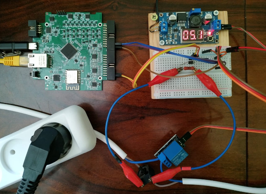
- Fork;
- Breadboard;
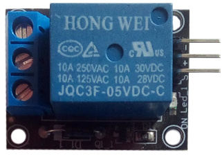
- Relay;
- Set of wires.
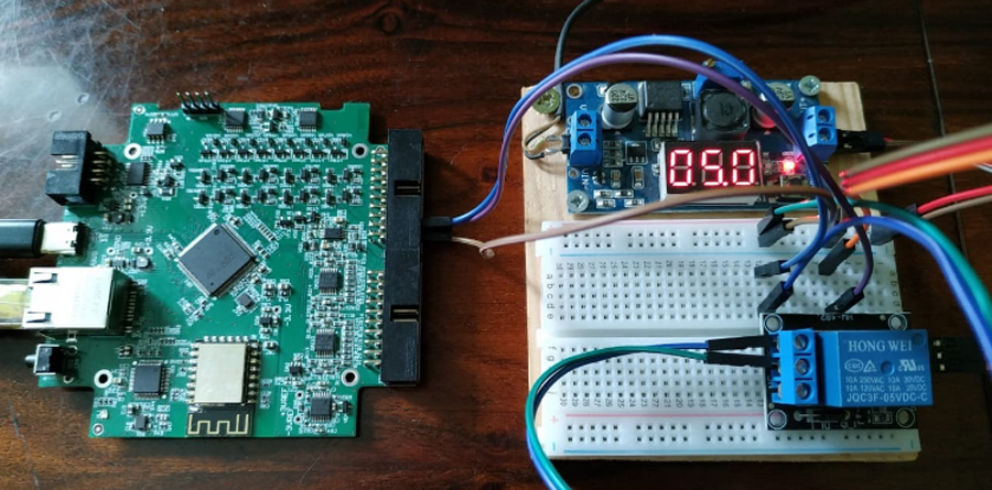
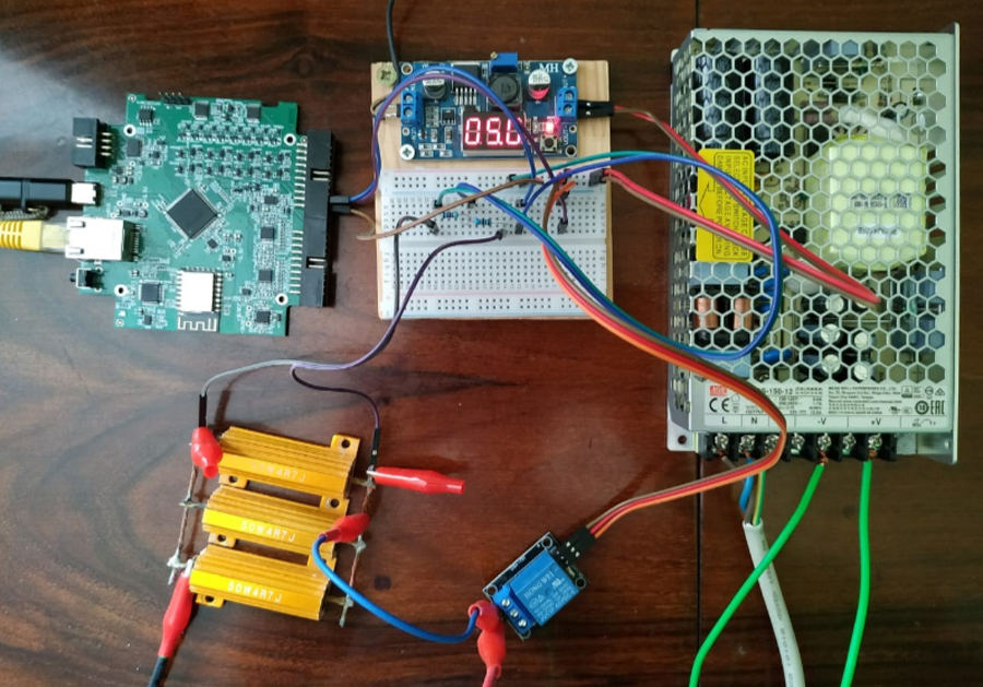
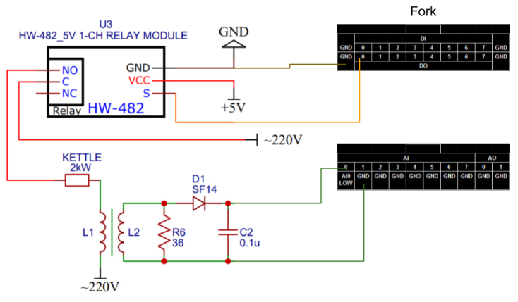
Assembled a circuit to test the relay at idle.
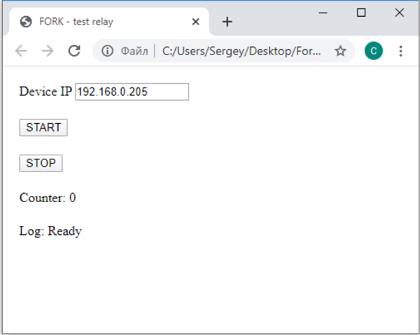
All commands are sent in the browser address bar.
To check the link, I enter the command
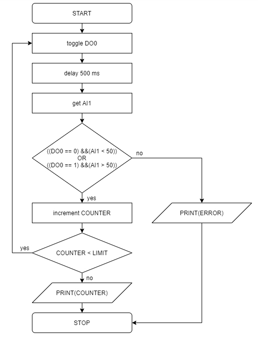
http://192.168.0.205/control?DI0http://192.168.0.205/control?DO0=1http://192.168.0.205/control?DI0In order to automate the relay switching process, I wrote a script in javascript that will switch relays in automatic mode and check the result. If a switch occurs, the script will increment the counter. Otherwise, we would see an error message and process would stop. Also, the script will constantly display the counter value. LINK.
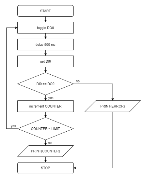
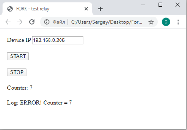
Started the process. For the test, I simulate the sticking of the relay by disconnecting one wire from Fork. I see that the process has stopped at the point of 7th iteration. I can also see an error message.
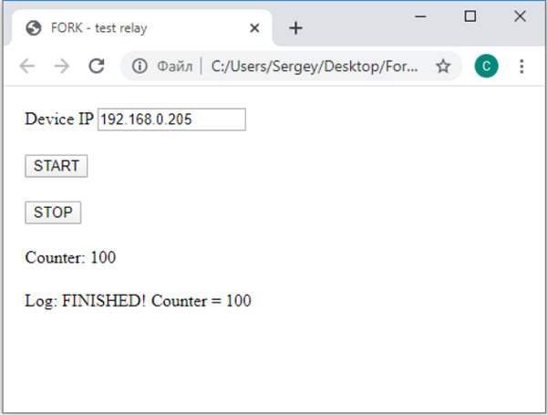
We’ll have to wait about 14 hours.
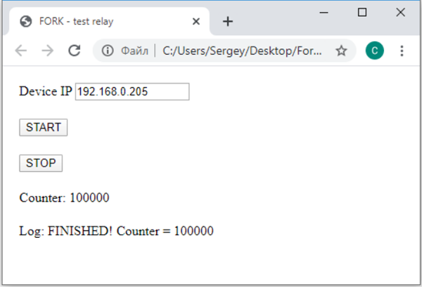
In 14 hours I will see a “success” notification. The relay has completed 100,000 switches.
In this case, we will also be needing:
– Power supply unit 12В/10А;
– Load resistor 1.5 Ohm 100 W;
– Wire set with section 0.75 mm2;
– Two resistors rated 6.8 kOhm and 4 kOhm.
Note – as a load I used 3 resistors rated 4.7 ohms, connected in parallel. Equivalent resistance is 1.56 ohms, which corresponds to a current of 7.65 A.
http://192.168.0.205/control?DI0http://192.168.0.205/control?DO0=1http://192.168.0.205/control?DI0I run a script.
The relay again has completed 100,000 switches at a load current of 8 Amperes.
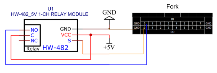
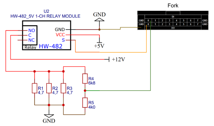
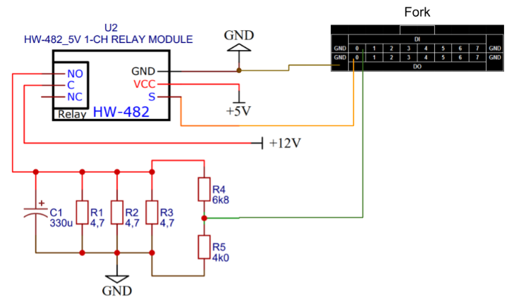
Here is the circuit.
To verify, I enter the command
http://192.168.0.205/control?DO0=1http://192.168.0.205/control?AI1I’m re-writing the script. LINK
COMMENTS