The idea was to make the actuator controller with some degree of automation and fully configurable through the web interface. The logic of the controller is stored in a file on the SD card, and not in the code, which makes it very easy to modify the logic of work, without changing the code and flashing the controller.
Since I really didn’t want to create web pages in code, I had to rummage through the vastness of the network and dig out such an interesting project – TinyWebServer. With this library, the logic of the controller is now completely separated from the display of pages. Arduino does not form pages completely. The interactive part is generated in the browser.
All pages, scripts and other information (in my case, all controller settings) are stored on the SD card.
Composition
1. Mega 2560
2. Ethernet+SD shield
3. Shift registers 74HC595 (the controller can support a large number of registers, but there is a limitation on the amount of RAM, since names and settings are loaded into RAM).
4. For logic processing, it is possible to use as input signals:
a) free Arduino digital inputs
b) analog inputs
c) digital inputs connected via 74HC165 shift registers
d) you can also add any types of sensors directly in the code to suit your needs (I will describe below How can I do that).
What the resulting controller can do.
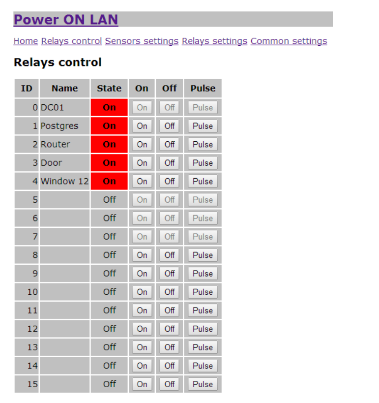
1. Manual output control mode implemented via the WEB interface (Enable/Disable/Give impulse).
2. Turn-on delay after power-up. If a turn-on delay is set, then the logic rules for this output do not apply and the relay is controlled only in manual mode.
3. Output control using logical rules, in which you can use any type of sensor, logical operations NOT / AND / OR and brackets. The formulas use sensor IDs, which are also configured via the WEB interface. For example, you can write the following formula (0|1)&!2. To bring the value of analog sensors to a logical value, two limit values are used to provide hysteresis. If the value is greater than or equal to the upper limit value, then the signal value will be true, and if it is less than or equal to the lower limit, then false. For all sensors it is possible to use value inversion. For example, when a button is connected, if it is not pressed, the input will be logical 1 (true), and when the signal is inverted, true will be processed when the button is pressed, i.e. at logical 0 at the input.
4. Sending SMS via SMS provider when switching on and switching the relay. Unfortunately, it doesn’t work very well, so it’s best not to use it.
5. Can work without Ethernet shield, only with SD. To do this, comment out the #define WEB_INTERFACE declaration . In this case, you can change all settings and operation logic by editing files on the SD card.
How it all works.
Working with the 74HC595 output shift registers is organized through my SPI595 library. The registers are controlled via the SPI bus with device selection on pin 7 (#define SPI595_CS 7).
Working with the 74HC165 input shift registers is organized through my SPI165 library. The registers are controlled via the SPI bus with device selection on pin 6 (#define SPI165_CS 6).
The Ethernet shield W5100 works with the standard library (#define ETHER_CS 10).
The SD card works with the SdFat library (#define SD_CS 4).
When the controller is turned on, information is read from the sett.txt file. Based on this data, the Ethernet shield, shift registers and global variables are initialized. If the SD card is not initialized at startup, then LED 13 will blink rapidly.
Then the relay and sensor settings files are read. When loading rules, they are automatically converted to reverse Polish notation, for quick calculation void prepareRPN(byte idx, char* formula)
Calculating the value of a logical expression after that becomes very simple. The following is a function to calculate a formula represented as reverse polish notation.
Adding your own sensor type
Define its type and attribute in constants:
Implement its code in a function
Load its properties and initialize it in the function void loadSettings(bool all)
Correct sensett.js for correct display in the browser.
WEB interface
Actually, from the very beginning, I took an example from TinyWebServer as a basis.
Screenshots


Controller polling frequency is 0.4 seconds.
After changing the settings of relays or sensors and pressing the Save button, the changes take effect immediately. General settings are applied only when the controller is initialized.
For the future
1. Since I have practically nothing with web programming, I did it as simply as possible, without frills. Everyone can fix files for themselves. You don’t need to edit anything in the sketch code itself. Actually for the sake of this all this was started.
2. When downloading data, the browser constantly requests all the data. And since jquery.js is used, and it is quite large, I would like to force the browser to cache it (and even better all htm and js files) for the entire session. Then the arduino would only send settings files and the status of relays and sensors. But so far, alas, it hasn’t. If anyone can tell me how to do this, I’d be grateful.
3. There are no checks in the analysis of the rules, so if the formula is incorrect, then the consequences are unpredictable. Perhaps someday there will be a rule check.
4. Make command control via com port. In principle, I have a class for this, but so far I have not connected it to this project. Something like:
relay 1 on
OK
get relay state
relay 1 ON
relay 99 OFF
5. Add variables for storing logical expressions so that in logical rules it would be possible to use not only sensor IDs, but also variables, for example, (0| A)&!2, where A is a variable whose value is being assigned by another formula.
Now, of course, you can get out of the situation by connecting the output of the 74HC595 to the digital input of the Arduino or to the input register of the 74HC165.
6. Make inputs counters…
7. Make several types of exits. Not only through the shift register, but also directly control the digital ports of the Arduino (there are enough of them in the Mega2560).
8. Make not only Init state for exits, but also init pulse.
9. It is possible to implement MODBUS, but this is the last.
10. Implement the input as a logic function from the real time clock, and as a timer function.
Bugs
When enabled, the output registers turn on chaotically. And since the controller is initialized for some time, the output relays can be turned on. So far, the register reset scheme has not been implemented.
After uploading the sketch, sometimes SdFat is not initialized for some reason. You have to reset the controller with the reset button.
One important point.
Everything is connected via hardware SPI.
Actually connecting the Ethenet shield, SD shield and 74HC595 does not present any difficulties.
The problem was to connect the 74HC165. The output of this register cannot go to the Z-state (someone saved on a pair of transistors 🙂), and when connected directly to the MISO, it makes it impossible to work with other devices. Buffer 74HC125 was used to solve this problem. It is controlled by the output defined by the constant SPI165_CS.
Register connection diagram

Total
In principle, already now on the basis of this controller it is possible to implement some fairly complex automation. And if you can edit the web interface without interfering with the code, you can implement a convenient user interaction. The only problem is that when working with the web client, the controller is fully occupied and cannot respond to changes in the state of the sensors (for this I wanted to force the browser to cache data for the entire duration of the session), so sometimes there are delays. I don’t plan to move logic processing into a timer yet, after all, this is not a real time device.
Links
Project
https://drive.google.com/folderview?id=0B7NuO_z3PX3NUTNncGw0VzQwRTQ&usp=sharing
The LIB directory contains libraries that make it easier to work with registers.
HTML contains the web interface.
TinyWebServer
https://github.com/ovidiucp/TinyWebServer
COMMENTS