1. INTRODUCTION
1.1. Overview
A smart home is an automated and intelligent home which can be designed and set due to the technology being used [1]. Smart homes can be programmed to fit the client’s needs. Programming can lead to a fully automated system where every device in the home can communicate with others via sensors. A smart home can provide good security, convenience, entertainment, good communication, economy and an information system [2]. Different smart house systems have been made where the control is through Android applications, Bluetooth, WIFI, web, call and/or short message administrations (SMS) based through GSM808. WIFI capability is great and the vast majority of current devices can be connected easily and coordinated so as to reduce the system’s costs. Bluetooth’s range, however, limits its usage to inside the home [3]. Several methods can be used to secure a smart home, such as: RFID, Password or fingerprint. These smart homes serve well in pre-alarming and controlling the temperature, air-conditioning, bulbs equipped with sensors, gas detecting sensors and flame sensors. As well as all this, a smart home alerts the home owner to thieves and burglars, several unwanted conditions with the use of IR waves. Furthermore, smart home sensors take
advantage of different ranges of electromagnetic waves including GSM, IR, Bluetooth and Wi-Fi. With these different frequencies a home’s devices are connected in a Wireless Home Area Network (WHAN)[4].
2.1. Smart Home System
Our system runs with Operating Systems (OS) such as Android and the Internet of Things (IoT), which are well known to those who deal with such systems. We have endeavored to abide by the limitations of commonly used systems. Comfort, security an flexibility are some common features of the system[11]. This system is able to work with android phones, laptops, tablets or a PC. The main components are: a board of Arduino (MEGA 2560& Uno R3), which can be called the brain of the system, a Router, Wi-Fi (Node MCU ESP8266-12E and ESP8266.01) with a good range, an IR device, an Ethernet shield (network interface W5100), a GSM device and a User device with an Android OS, such as smartphone or computer (through the web). These devices are connected through either the internet or Wireless Application Protocols (WAP). The user controls the entire system through an android enabled device (by either a smart phone or tablet). The system is also controlled through an IR device (control). This has made the system more desirable and famous, as it does not necessarily need the internet or a wired
connection. The Wi-Fi network is the main grid. Through it, the instructions of the user are transmitted. Bluetooth and IR are also used inside the house as alternatives when needed despite their specific importance. The user’s necessities are the foundation steps that the system is built upon (Figure 2.1).

2.2. Wireless Sensor Network (WSNS)
WSN is a collection of many sensor hubs. Each can sense, process and connect to a microprocessor unit to work together in a coordinated manner (Figure 2.3). Physical or environmental conditions, such as motion, temperature, humidity, smoke and gas, etc., are monitored by these sensors in a coordinated way [13]. These sensors run through an algorithm to the main control unit (Arduino Node MCU ESP8266-12E), which has much more computational power and links and acts as the main way that links the sensor nodes and the end users. The principal features of WSN include power consumption constraints for node; capability of accommodation with node and communication tasks; scalability to large devices; ability to resist hard environmental conditions, mobility of node and variation of nodes [14]. It is the WSN that plays a major part in enabling highly accurate sensor and actuation systems, in homes, buildings and surrounding spaces, by supplying a trusted, cheap and wide solution. Their tools can be used in current, as well as future, structures, without significant changes in the existing infrastructure[15].

2.3. The Internet of Things
The Internet of Things alludes to a system of items where everything is extraordinarily and generally addressable, distinguished and overseen by PCs and advanced mobile phones. It is a gathering of advancements that make it conceivable to interface things like sensors and actuators to the Internet (Figure 2.4) [16][17]. Internet of Things is known as an incorporated piece of the Future Internet and could be characterized as a dynamic worldwide system foundation with self-arranging capacities in view of standard and interoperable correspondence conventions where physical and virtual things have characters, physical characteristics and virtual identities, and utilize smart interfaces, and are flawlessly coordinated into the data network [18].

2.4. System Block Diagram
According to the design needs and desires, the system block diagram (Figure 2.5) is made. Our block diagram shows all the parts of the system and their functions. The project design follows the modular approach, using an Arduino Mega 2560 (Atmel 2560) microcontroller. The system is intended to enhance security, adaptability and effectiveness. The framework is planned to give ease in everyday life, and additionally spares power and human endeavor. This framework incorporates Arduino, sensors (like LPG gas, PIR, humidity and temperature), LCD show, LAN, 8 Relays channel, RFID, Keypad, smartphone and PC.

2.5. System Implementatinons
2.5.1. Project Flow
This section explains the steps that need to be undertaken in order to achieve the goal of the project (Figure 2.6).

2.5.2. Hardware Implementation:
This includes PC, Laptop or Tablet, and Smart Phone, Arduino Mega 2560 (Figure
2.7), Arduino UNO R3 (Figure 2.8), Breadboard Circuit, Ethernet Shield, Router, Led, LCD for Arduino, LDR Sensor, RFID Card System, Motion sensor, Servomotors, Temperature sensor, GSM Modem, smoke sensor and LPG gas sensor.
2.5.3. Arduino Mega 2560
My project uses an Arduino MEGA2560 which is based on an ATmega2560 microprocessor.
2.5.5. WiFi Shield (ESP8266 WIFI SERIAL TRANSCEIVER):
The ESP8266 Serial-to-WiFi adapter has been widely adopted as a cost-effective solution for IoT and WiFi-capable devices. We used two types of ESP8266 in our project: Node MCU ESP8266-12E WIFI (Figure 2.10), (Figure 2.11) ,and ESP8266-01 WIFI [21][22].

2.5.6. Bluetooth HC-5
Bluetooth is a short field communication technology (less than10 m) and is considered a low energy utilisation. It is not appropriate for all our demands. The information transmission rate is less than that of WI-FI, yet it is still beneficial for our application (720 Kb/s) (Figure 2.13) [26].

2.5.7. SIM808 Module (GPS-GSM-GPRS):
This is a GSM, GPRS and GPS three-in-one limit module. In light of the latest GSM/GPS module SIM808 from SIMCOM, it supports GSM/GPRS Quad-Band framework and joins GPS innovation for satellite route (shipping). It is controlled by AT charge by methods for UART and sponsorships 3.3V and 5V clever level (Figure 2.14) [28].

2.5.8. Ethernet Shield (W5100)
In our design, W5100 interface has been used (Figure 2.15) this uses 0.18 μm CMOS technology and has 16Kbytes of memory (TX/RX buffet) to supply a 10Mb/100Mb Ethernet association [29].

2.5.9. LAN Cable (Local Area Network):
To get to the web in Arduino LAN connection is required. The LAN speed is considerably quicker than the wireless speed (Figure 2.16) [30].

2.5.10. LCD Display
LCD display is used to see the present status of the home devices and the sensors (password and temperature) (Figure 2.17).

2.5.11. Sensors
The sensors used in this project include photo resistor (Figure 2.18), temperature and humidity sensors (DHT11) (Figure 2.19), flame sensor (Figure 2.20), Gas Sensor (MQ-2) (Figure 2.21) and Human Body Pyro electric Infrared Sensor (PIR) (Figure 2.22). There are many distinctive gas sensors that recognize LPG, CO2, methane and fire. The case given here utilizes the MQ2 sensor to distinguish air quality.

The following flowcharts show different sensors and their connection to the Arduino and how temperature, humidity and gases are detected (figure 2.23 and 2.24).

2.5.12. Software Implementation – System Software Design
This part deals with the configuration of the software, program procedures andframework approaches used in programming the Arduinos in our smart home model. The software program roles are receiving information and orders, performing distinctive orders, controlling operational stations and supporting information input/output gates. We have attempted to offer general thoughts on program stream and usage (see flow charts). We divided our design into various parts, contingent upon the useful connection between these parts, to be dealt with easily and when a section or a piece is not working appropriately, it can be detected and treated.
1. TP-Link Router that boosts wireless network throughout the home, broadcasting WIFI that connects Node MCU ESP8266-12E, ESP8266-01 to smartphone and PC. The
Router is also connected to the Ethernet shield via a cable (RJ-45), connecting it to an Arduino.
2. The GSM 808 communicates with a saved mobile number during any event that reaches an Arduino through any connected sensors. When you are outside the home, the communication is through the Internet. Via IoT we can control home devices (e.g. lamps and TV) from far away.

3.1.1. An Entrance to ESP8266
Its price is around $4 to $10. It has many types, each with different features. For this
project, Node MCU ESP8266-12E (Figure 2.11) and ESP8266-01 (Figure 2.12) are used. It is
achieved easily. It can be used in larger projects to tie several devices and for controlling them.
The Node MCU ESP8266-12E type is used the most. It is feasible in terms of running the project.
Note: If anyone wanted to use fewer pins then ESP8266-01 is a better option as it is smaller and cheaper (Figure 2.12).
Warning: It is worth pointing out that these pieces work at 3.3V. If the voltage is higher then the circuit is harmed with the possibility of defecting the entire system.
3.1.4. Methods of ESP8266 Programming:
Two ways are most often used to program both types of WiFi Node MCU ESP8266-12Evand ESP8266-01. In the first chapter, the methodology of its programming and the preparation to run it and install Code for it [40]. In section one: ESP8266-01 is described via the Arduino IDE program.
3.1.5. The requirements for their operation
Installing Java in the PC when the PC lacks Java. The most updated version needs to be installed. It can be downloaded via the following link. https://www.java.com/en/download/ Install Arduino program, correctly. Then, install ESP8266 board as the following, It is important to recognise each pin. In the following table, the GPIO pins explained which each one of them with the ESP8266-01 only there are 0,2 pins. But, in Node MCU ESP8266-12E there are 16 GPIO pins as input. The selected output works at 3.3v.
Step 2: The following figure indicates the ways they are assembled together (Figure 0-6) and it performs the following tasks:

Step 3: It is necessary to import this library for the project to work best, especially for the GitHub. It is added to the Arduino program: https://www.arduino.cc/en/Reference/Ethernet
Step 4: Then the code of the program is written. Then, the port and the Arduino type are determined and uploaded. Then, it is saved as (Ethernet).
Step 5: This is the program code at the end of the project.
3.5. This section of the project is specific to [Control the Home ]
Step 1: It consists of the following parts:
1. 1*Arduino (Mega-2560-R3)
2. 1*DHT11 Sensor ( Humidity & Temperature )
3. 2*Push Button
4. 2*Resistors (10 Kohm Used) // used to LCD Low or Height Light
5. 1* 3 mm LED- Green
6. 1* 3 mm LED- Red
7. 1*Buzzer
8. 40*Jumper Wire (male + female ) 20 cm
9. 1*Bread Board (Size 16,55 x 5,45 x 0.85 cm)
10. 1*Battery 9V
11. 1*Battery-9V-DC-Power-Cable
12. 1*USB Cable
13. 1*Laser
14. 1*LDR
15. 1*LCD
16. 1*RFID
17. 1*Keypad 4*4
18. 1*Relay 4 Channel
Step 2: To buy all the parts used in the project – from the following link at the end of the project.
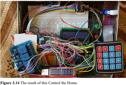
Step 3: The following figure indicates the ways they are assembled together (Figure 3.14) and it performs the following tasks:
Step 4: It is necessary to import this library for the project to work best, especially for the GitHub. It is added to the Arduino program:
Step 5: Then the code of the program is written. Then, the port and the Arduino type is determined and uploaded. Then, it is saved as (Control the Home).
Step 6: This is the program code at the end of the project.
Step 7: The result of this section is shown in the following figure.

4. EXPERIMENTAL RESULTS
The planned procedure in building the smart home was successfully applied using equipment such as: WiFi, Sensor, GSM and Arduino in order to operate and administer all the instruments properly.
– The house can detect any body approaching it through PIR or LDR and Laser.
– It can be operated using a personal password by using RFID or Keypad, which turns on a green light that can be seen in the LCD screen.
– After entering the Password or the RFID the door opens automatically and then.
– In cases of entering incorrect passwords or using the system incorrectly, a red light and a buzzer turn on to give warning. It enables the user to switch the lights on and off. It also works automatically by turning the indoor and outdoor lights on when it is dark and turning all of them off when there is daylight.
– It also enables the user to check the temperature and humidity in the house, as well as working sensitively to detect any strangers entering the house and the existence of any gas, CO2, or fire. It also operates to take some necessary reactions and giving the user caution through their mobile phone, as well as operating ventilators and contacting related parties such as fire rescue services, police and ambulance.
– It is worth mentioning that the results can be accessed through web, smart phone and tablet using Bluetooth, WiFi, and IOT.
5. CONCLUSION
– Nowadays, technology has developed in so many ways. In this respect, smart homes could be built considering the following important points:
1. Making sure they are strong and effective as well as being user friendly.
2. Considering security and safety aspects.
3. Making sure it costs little and is economic.
4. For the development of this project, the Solar Tracking generation of light is used to save more energy.
5. Building in a way which leads to less energy consumption and is environmentally friendly.
6. Making sure it is easy to develop as well as easy to mend.
– Smart home is able to connect a number of machines and sensors together and enables them to work properly and automatically. It also facilitates its users, especially
disabled people.
– In this study, Smart Home Security is considered, so as to be applied properly. It suggests two different ways to connect it to internet, so that it can be used and observed from a distance. This can be achieved through the web by using a PC, laptop, smart phone and tablet after entering their special IP and connecting them together through WSN.
– The study also suggests using more than one type of wireless, such as IR, Bluetooth and WiFi, in the same project.
– In case of any unexpected incidents, such as strangers entering the house, the existence of fire, smoke, CO2 gas, or gas exposure, etc. the project suggests building a relationship between the smart home, its user and related parties through GSM.
– The study also focuses on protecting the environment, reducing electrical energy consumption and avoiding the waste of water. These are the main points, as the mentioned sources are among the main issues in our country as well as being the primary daily needs that are not available these days.
– It is recommended to develop this project and connect it to Face Recognition and Voice Recognition, which aims to enhance the facility and provide more safety and security at the same time.
COMMENTS