ABOUT THIS PROJECT
Background
For those how haven’t read the first part of the story.
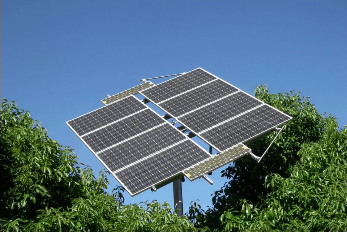
So as I am coming up to retrofit/overhaul time on the twins, for mechanical reasons the obvious choice is probably the south tower first. It was built with a reversed east-west mechanism. This was a bit of an experiment which served to teach me that there is a good reason for constructing things the “right way.” The “twins” are much smaller units being only 1.5KW each, detailed CAD drawings of these are included at the bottom of this project. The two towers feed a single dual input inverter located on the north tower. Each tower has its own battery set, solar regulator and tracking computer. They are however both feed from the same DC pony panels located on the south tower. Both of these are 24V systems not 12V like the east tower.
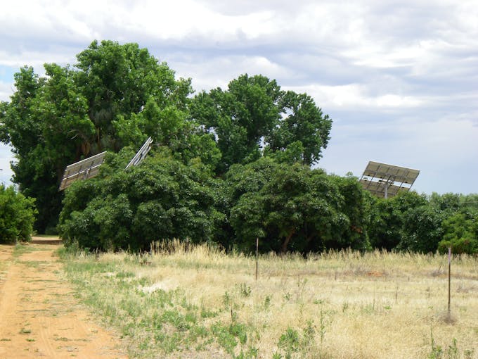
If your wondering why I’m replacing the optical trackers? This picture on a partially cloudy day shows the problem.
So on my Christmas list for this year was time and location from the GPS, network internet access (NTP time server) and maybe chatting to the inverter to get solar output. I also wanted the unit more compact, preferably in one box so I can mount on the back of the tracker frame much the same as the sensor in the first unit. Of course I’m determined to get the OTA thing right so I don’t have to go up on the power ladder with the laptop to change programs.
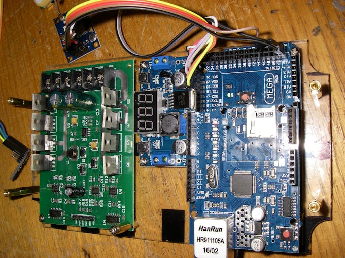
More Memory – Bigger CPU
With my UNO on the previous project packed to the rafters, it’s time to bring on the Mega. Other contenders for this job are the WeMos (ESP8266) but that will be for the next installment.
The great thing about the Mega chip is that it has four (4) serial ports, a sort of wet dream of serial communications in a chip. So I can hook GPS and inverter plus Bluetooth adapter and still have room for a diagnostic port.
It also has heaps more memory / code space, an essential item for generating a website on chip.
IoT to Replace GUI This Time
Yeah getting with the program, not putting a LCD panel on the unit this time. Little point as it will be up on the tower and you wont be able to read it. Beside thought it might be fun to hook it to the internet and let people see it for a while.
The Code
So we lost 80% of the original code which was GUI. So we gained back a heap memory space removing it but used a shipload more to run the web servers.
We you know how I said no LCD, well I usually cheat and use one during development. Especially as I seemed to have way to many bugs in the system.
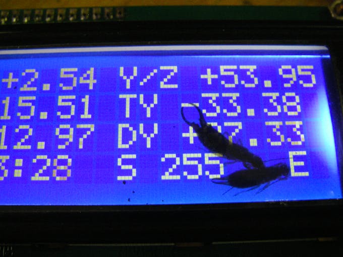
Anyhow this was a handy edition while I was getting stuff working. Easy to unplug and the I2C code can actually left in place so I can always plug it back in for bench testing.
I used the TinyGPS as a parser on the GPS NEMA stream. This picked out the 3 bits of information we need for the tracker from the vast array of data available from the u-blox. Talk about using a sledge hammer to crack a peanut, buy hey you can make damn smooth peanut butter while your at it. The GPS lock part seemed quite important it determining if the data was valid so I thought I might indicate the number of satellites on the meatball by lighting up the corners progressively.
Being a newbie to Arduino IoT, the first thing that happened writing the web pages was I ran out of variable memory. Hmmm, how could this be so? I didn’t use many variables of significance. After a bit of bit of “jiggery pokery” and some reading, it turns out the “F()” macro is a handy bit of kit and you should not leave home without it. This tucks Strings back in the “code segment” where they arguably belong. You can see these sprinkled liberally through the code. I dare say it slows things down a bit but I’m tracking the sun not an incoming skud missile so a few extra ms won’t hurt.
I must apologize for the web page design, very used to using ASP on a behemoth which is largely running at idle to generate my pages (I’m an old school pure HTML fan). In Arduino land the poor old CPU is screaming it tits off to generate a basic page. A better approach would have been to offload to the web browser using javascript as the host CPU is most likely packing at least 10 times the computer power of the Mega. That said my page is compatible with 99.9% of all devices/browsers as it is pure HTML and requires no other online services to generate. Perfect for stand alone applications.
The web site is also a first cut as I’m still working out what methods work for me in Arduino land. So there are lots of remnants of code samples Frankensteined together with just a little bit of me showing through.
The time stuff was a bit daunting, as there seem to be so many standards and bits to pull together. In the end I managed to work out the how’s and why’s of each part and got the calculations all onto the same time zone base no matter what the incoming source of truth. The tracker uses GPS over Internet NTP over external RTC. This is overkill but the code is written so you can remove a time source in the hardware build and the software is largely OK with that. One issue is that once you tie to a real time source you cant cheat and just put the clock forward to bias the array or compensate for angular offsets. You actually have to use the angle offsets as the clock become an absolute not a variable.
WiFi
Got a working web interface done only to find I really wanted it to be WiFi, talk about any roads and unknown destinations! So Back to looking at the WeMos, Either as shield or a stand alone interfaced via serial or maybe modbus RTU. Another choice was an external ether net bridge, power being the only issue as the one to hand draw around 100 mA. Mind you after a few measurements the arduino ether net shield turns out to be a hungry beast as well.
From my first experience ESP8266 it really seemed to struggle to generate pages, mind you I’ve prolly been using the wrong end of the screwdriver. Definitely an example for where you should off loading the processing to a better CPU or in my case just hold the screwdriver the right way up!
My eBay addiction meant a new WiFi module turned up in short order, it has just a uart, level shifters and that’s it. Hooking this to a CH340 and sending it AT commands from one of my favorite tools reveled where and how the time is lost. These work brilliantly if you organised and can spit out all the response in one go, not so good for build on the fly as there is a large sending overhead as you swap modes for sending. This differs from the Arduino ether net shield which does not seem to be as effected, no matter how small a chunk you send. So with lesson learned I got the tracker configuration page generation down from 10’s of seconds to seconds. Again this was done in a proof of concept code first before I hacked into the already working Ethernet shield version. The final result being two versions of code for the Mega, one for Ethernet shield and one for ESP WiFi serial adapter.
Enclosure
I decided to put all the electronics except to fuses into a single box which had a clear lid, this allowed me to see my led matrix from underneath. The web interface allows me to swap X-Y axis and flip +/- so I can place the unit anywhere and still have it work.
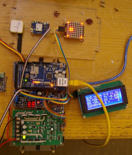
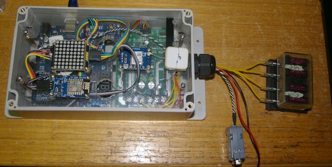
Clear acrylic sheet was used as a chassis for mounting all the boards too as I wanted this to be transparent to both light and microwaves. One issue I hadn’t tested for is if a GPS can see through solar panels, had a plan B of external antenna in mind however. The single chassis layer rapidly turned into 2 layers with all the extra hangers on required for feature creep.
The Ethernet shield was a bit of an ops moment, RJ45 connector up against the edge of the enclosure. Hmmm perhaps we need to change the socket to a vertical mount one or change to a different type of shield which can be mounted on the top layer of the electronics. In the end I split the code into two versions the ethernet and the ESP connect via serial interface. Same web site different output interface.
I thought I would have tons of room in my big box but feature creep is a killer, power supply, RTC, matrix display, GPS and Bluetooth module. One of my colleagues always advises leaving 25% extra enclosure space, that’s fine as long as you don’t want to put 30% extra in 🙂
On the towers, actuator cables to the N/S and E/W motors on the tracker have to be re-routed, much less cable is used as they don’t need to connect to the control box at the base of the tower. The fuses will mounted externally as we just ran out of room in the box, no big deal and also makes a nice point to disconnect the unit for service. I’m going to run a temporary power cable and attach the unit to the underside of the tracker and do a burn in test. I’t will be working but not connected to the motors. I can monitor it and make sure it’s 100% before swapping over.
Power consumption be the only issue that has arisen. The total power consumption is higher than desired. I actually thought there might be a short circuit but did some measurements on the input supply at 12V and found.
- Total power consumption is 250mA, which in this day and age is high.
- GPS 60 mA
- WiFi 60 mA – these two are responsible for nearly 50% of the burn!
- LED display 10-20 mA
- Sensors 20 mA
- RS-232 10mA
- What’s left (Mega and H Bridge) 90 mA
Now at 24V whole lot draws about 150 mA so our overnight burn would be between 1.2 to 2.1 AH depending the season.. Hmm we need that to fit in our 20% depth of discharge for the 7/9AH battery. Well almost but if you apply the magic factor of 6 for solar design I need to boost the battery to 20AH ish (not happening!).
So – I think this might be a suck it and see moment. Possible outcomes to come:
- I can put all the code in an ESP chip and save bucket loads of power.
- I can implement so power saving code to turn off the GPS overnight.
- Could run the system without GPS and use the NTP over WiFi to get the time?
Stay tuned for the next installment!
COMMENTS