_yHxMSA5TEE.jpg)
![]()
The programmable bench power supply (PSU) is an attempt to bridge the gap between so many simple hobbyists/DIY power supplies and commercial solutions trying to combine the best ingredients and practice from both sides. The former solutions are in general open-source with a limited feature set and without support for some standardized way to communicate with them (e.g. SCPI). The later solutions are costly and not open (and easily “hackable”).
This is an ongoing project and our aim is to provide a solution that is comparable to commercial solutions and it’s completely open (software and hardware) so that anyone can freely replicate it or use some of the building blocks for making new solutions.
Currently, we have three working prototypes. We named the latest prototype EEZ H24005 which stands for hybrid, dual-channel, 40V and 5A.
From the very start, we tried to make it modular. In that way would be much easier to understand how it works, and assemble and repair it. Currently, it’s consists of three PCBs:
- Auxiliary Power Board
- Power module (2 is required per unit)
- Arduino shield for digital control
As a power input, it’s possible to use an affordable toroidal transformer with dual secondary coils or two 48 V AC/DC modules.
To further simplify its building we succeed to reduce the number of wiring to the minimum. That is accomplished by grouping all control and output power lines to the single connector on the Power module, and two of them are directly plugged into the Arduino shield that is mounted directly on the enclosure front panel and carry a 3.2″ TFT colour touch-screen display from one side and Arduino Due from another.
The TFT display is used as the only local user interface. No additional switches, potentiometers or keypads are required. A lot of space is saved on the front panel in that way, yet it allows that all functions for both channels can be easily accomplished from a single place.
The block diagram that shows all important components are shown below.

Auxiliary Power Board:
.jpg?auto=compress%2Cformat&w=740&h=555&fit=max)
This board is used to accomplish the following:
- AC input protection
- AC power soft-start/stand-by
- +5 V for Arduino shield supply
- carrying Ethernet and USB connectors (with an option to isolate USB) and
- 12 V cooling fan control
It’s intended for mounting (with help of a few metal spacers) directly on the enclosure rear panel. Dangerous mains voltage is present only on this board and it works with both 115 and 230 VAC (50/60 Hz).
Power Module:
.jpg?auto=compress%2Cformat&w=740&h=555&fit=max)
The power module’s main purpose is to provide reliably on its output regulated output voltage and current. Most of the important parameters that are usually measured to find out a power supply performance depend on this module design. The current version (r5B9) is a result of many iterations and great feedback from various people on a few forums. We believe that this most challenging part of this PSU could be further improved in many ways: e.g. by lowering BOM count without necessarily decreasing overall performance, decreasing ripple and noise possibly with four-layer PCB, etc.
Its power stage is divided into two sections: pre-regulator that is built around LTC3864 buck/step down controller and MOSFET post-regulator that is based on excellent work of. This hybrid design comes with one interesting feature: low-ripple mode of operation thanks to the used LCT3864 that works with P-channel MOSFET and allows “100% duty cycle when the pre-regulator circuit is in fact by-passed and hard to filter switching noise is decreased on the output. Entering that mode of operation is managed by MCU and it’s in line with pre-regulator’s switching MOSFET and post-regulator pass MOSFET SOA.
This module also has a bias power supply that is used for powering all analog and digital controlling circuits. It provides +5 V, -5 V for op-amps that are used for CV (constant voltage) and CC (constant current) control loops, and +5V for digital section (ADC and 8-bit I/O expander). Additionally, its provide -9V that is required for the so-called “down-programmer” (DP) circuit. The DP is used to speed up output voltage programming when new set voltage is lower. The biased power supply also provides a power good signal that is used to indicate MCU the “health” of the controlling circuit’s power.
The Digital part of the module provides 16-bit programming resolution of both voltage and current using DAC8552. Currently, the output resolution is firmware limited to two decimal points (10 mV, 10 mA) and leaves enough room for better precision (down to 1 mV, 1 mA full scale). The ADS1120 offers a 15-bit monitoring resolution of programmed (DAC outputs) and actual (post-regulator outputs) voltage and current.
The power module also has an output-enable (OE) circuit. That function could be achieved by programming output voltage to zero, but in this way, it’s possible to easily add a manual switch independently from MCU operation (as an extra measure of precaution in case of failure).
Remote voltage sensing is also implemented as an important feature when the accurate output voltage is required with a high current to compensate for voltage drop on the wiring between output binding posts and load terminals. It’s complemented with reverse polarity protection when Sense input is mistakenly connected to the power output of opposite polarity (e.g. Sense+ to Out- and/or vice versa). That will result in an instant increase of the output voltage that could result in connected load damage if the current limitation is not set. Thanks to this circuit output voltage cannot exceed approx. 1.5 V (so extra precaution with wiring is still needed when remote sensing is selected).
Finally, the power module offers remote voltage programming when the external analog signal is used to set the output voltage.
Arduino Shield:
.jpg?auto=compress%2Cformat&w=1280&h=960&fit=max)
The Arduino platform is initially chosen for digital control for the obvious reason: it is widely available, many people are already familiar with it and it represents a great user community helped that its IDE and libraries offer many building blocks that can save a lot of development time. As time went by, however, it became increasingly clear we’ll reach its limits on both sides: hardware and software capability.
We started with Arduino Leonardo which was enough for driving LCD 128×64 display and no extra libraries as one for the Ethernet communication. The Mega2560 was the next candidate that is used to drive 240×320 colour display among other stuff, but latency is visible and to great extent tolerable. But its modest 8 Kb of SRAM requires lots of tricks that many processes can work within such limits. Finally, we come to Arduino Due, still the most powerful model in the “Mega” form factor, that also has enough I/O pins that is needed when as in our case a low-cost TFT display without a built-in processor is selected.
It might be easier and cost-efficient if the “shield” concept is not selected and the MCU is directly placed on the digital control board. But, on other side, it offers more modularity and leaves room for connecting a more than Arduino Due board in the future. Of course, the manufacturer is not necessarily Arduino.
The Arduino shield provides some interesting functionality that makes the PSU more attractive:
- Carry power output binding posts, and two channels outputs can be connected in serial or parallel thanks to built-in power relays and that activity is MCU managed for improved safety
- Compact push-in connectors are used to wiring remote sensing, remote programming, digital trigger and load temperature sensor
- Switching regulator’s frequency synchronizations
- WiFi module connection (optional)
- Incremental encoder input
- Soft-start/Stand-by control (located on Auxiliary power board)
- Beeper
- Analog inputs for temperature measurements
- LEDs as an additional indication for some key functions (i.e. CV mode, CC mode, Output enable, Remote sense, Remote programming, Stand-by mode, Serial/parallel coupling)
- Cooling fan PWM control and speed measurement
It also has hosts some parts that are missing or partially supported on Due:
- EEPROM storage
- Real-time clock (RTC) with supercap back-up
- Reset supervisor with watchdog
- Ethernet communication
- External Ethernet module connection (optional)
- External digital trigger
Software Support:
The major differentiator between this project and many DIY solutions is its software. That also makes it more similar to many commercial solutions with that exception that is and will stay open source. The software part currently has the following components:
- Firmware (works on both 32-bit ARM Due and AVR 8-bit Mega2560)
- Software simulator
- EEZ Studio
Development of the firmware starts from remote control, an unusual point for device that has local control. A SCPI programming is chosen and as command parser a forked version of Jan Breuer’s SCPI parser is used. The first version M1 (Milestone One) released in December 2015 offers comprehensive support for SCPI remote programming as described in SCPI Reference guide.
With SCPI the PSU can be seamlessly integrated into any laboratory environment and can be managed with SCPI controller’s such as LabVIEW (NI) or VEE Pro (Keysight), etc.
We are finalizing M2 that is bringing local control using the TFT touch-screen display. Here is a partial list of supported functionality:
- Various protections (max. voltage, current, temperature and power)
- Calibration (voltage and current)
- Soft-start/Stand-by
- User profiles
- Self-test, diagnostics
- Fan control
- Low-ripple mode, etc.
Another possibly unique feature of this project is Software simulator that is actually a by-product of firmware development. It’s created to speed up firmware uploading and debug procedures. With the Software simulator one can test all implemented functionality on any of the major OS without having a physical device.
%20small_2162x732.png?auto=compress%2Cformat&w=740&h=555&fit=max)
Software Simulator
The EEZ Studio is another software component that cannot be standardly found within the Arduino software framework. The Arduino IDE greatly simplified MCU software development but still does not offer a lot when e.g. one needs to design and animate GUI on colour touch-screen displays. Since PSU has a lot of options that require a lot of menus/pages on the screen to make it accessible and useful. At least we are not aware of such a solution and the partially open concept of e.g. Nextion is still not too attractive for us.
It’s a very frustrating task trying to guess when one or more pixels on the screen have to be changed. We made our situation even more complex with the decision to move from “portrait” to “landscape” display orientation in the latest revision and want to support previous prototypes. That is double the number of required GUI menus.
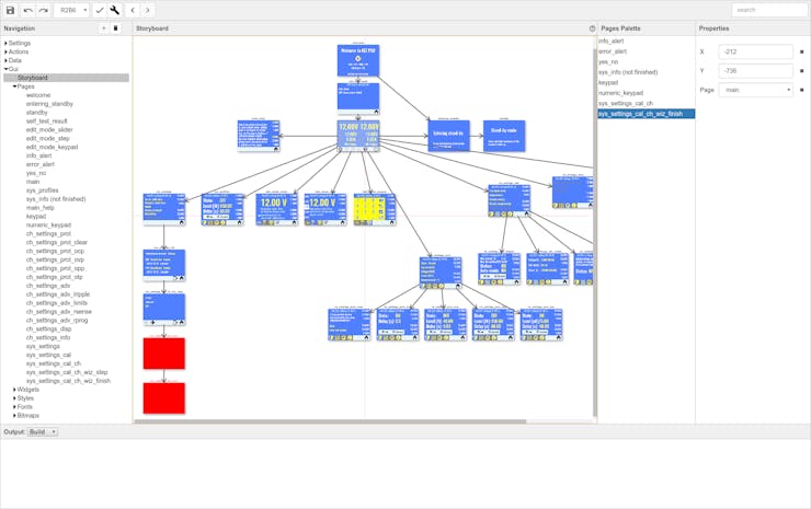
EEZ Studio Storyboard
The EEZ Studio in its current version (pre-GitHub 🙂 is helping us with the following tasks:
- Importing bitmap fonts, character map management and editing
- WYSIWYG editor of display pages in both portrait and landscape orientation
- Storyboard, a complete pages/menus structure in the single place
COMMENTS