Tried running the Arduino Ethernet library on Spresense. Actually, I had already run it before purchasing the LTE expansion board, but I will publish it including the library. Spresense is upward compatible with Arduino and feels very good.
Purchasing an Ethernet module
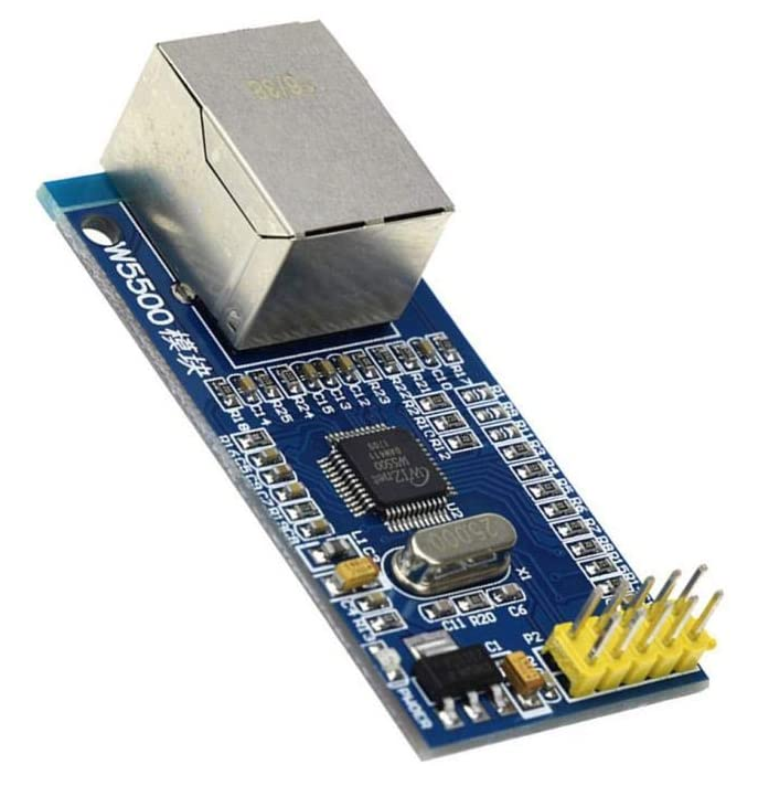
I could have bought an Arduino Ethernet shield because the Spresense expansion board is pin compatible with the Arduino UNO, but there are many other cheap modules out there and the shield’s ICSP connector was a hindrance to Spresense. I bought this. 1494 Yenya. If you look for it, there seems to be a cheaper one.
W5500 Ethernet Network Module
https://www.amazon.co.jp/gp/product/B07H3Z4FNX
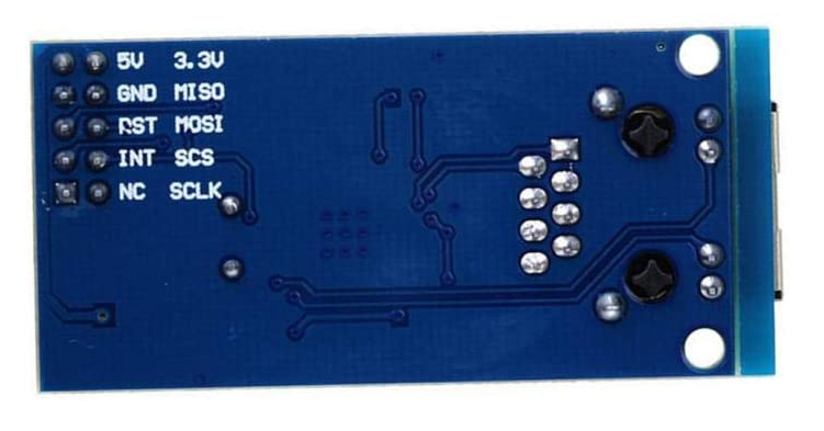
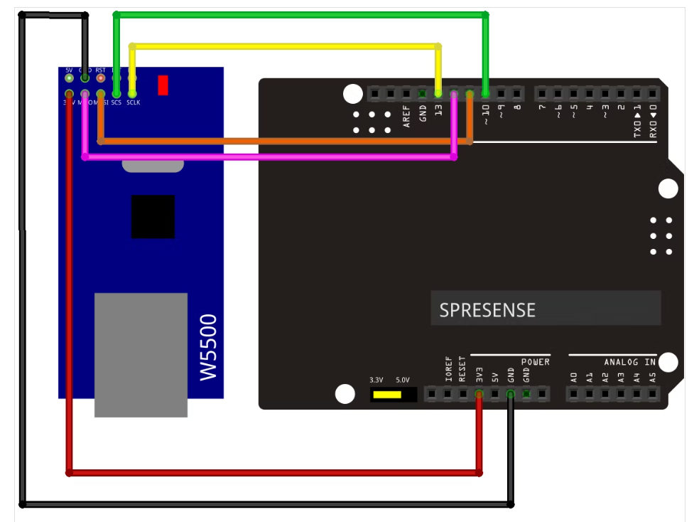
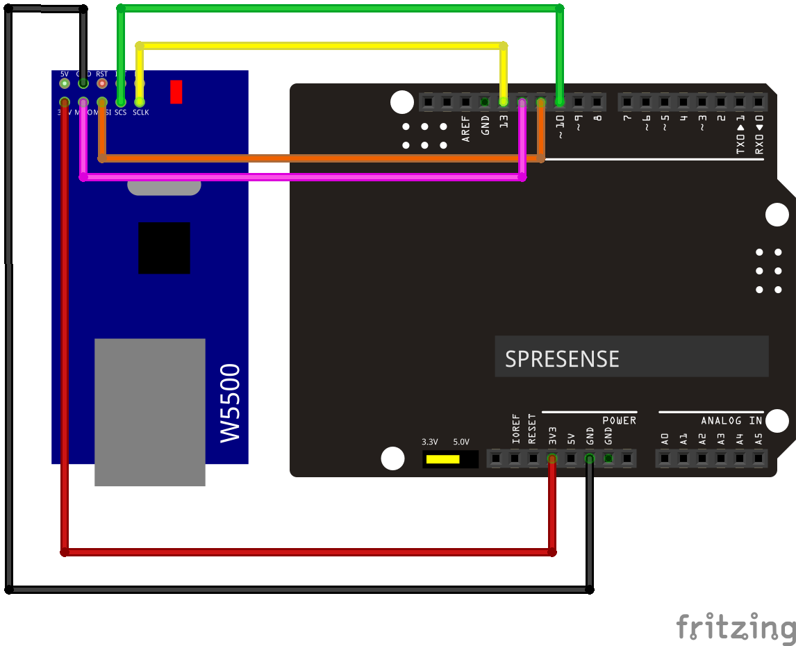
Connection between SPRESENSE expansion board and W5500 module
The operating voltage of the W5500 module is 3.3V, but since it is 5V tolerant, it can be operated with either 3.3V / 5V.
The figure below is an example of connection with 3.3V. At this time, don’t forget to set the jumper (JP1) of the Spresense expansion board to 3.3V as well.
Ethernet library porting
The Ethernet library is the one that is automatically included when you install the Arduino IDE, but
the source of the original home is here.
https://github.com/arduino-libraries/Ethernet
I had to modify the library a little to get it to work with Spresense, so I’ve uploaded the changes here.
https://github.com/baggio63446333/Ethernet
It would have been nice to change to more Spresense-optimized code, but I’ve only
made changes that take into account the ease of patching so that the differences are clear (as of May 01, 2020).
https://github.com/baggio63446333/Ethernet/pull/1/files
Please install it under the libraries folder of the Arduino environment. Since compatibility with other boards is guaranteed, there is no problem if you use this library as it is when you run it on another board. (If you no longer need it, delete the entire folder and nothing will happen.)
The point of Spresense transplantation is
- Use SPI_MODE3 instead of SPI_MODE0
- Hardware controls SS (Slave Select) without permission
- Buffer read / write to W5500 and do SPI.transfer () at once
- Disable interrupts during SPI.transfer () transfer (additional note 2020/05/07)
- When I was creating an IP camera with Spresense Camera, I realized that I needed to ban it. If you are writing a real-time application that cannot set a long interrupt disabled interval, it may be better to assign SS to GPIO and use it. SS can be assigned to GPIO by specifying a PIN number such as Ethernet.init (9); before Ether.begin (). Or, after all, it seems better to allocate network processing to the sub-core and offload because it does not impair the real-time performance of the main core. The design of the IP camera has been changed so that it is assigned to the sub-core.
About Spresense SPI
As for the SPI used in Spresense, you can see that ARM PrimeCell PL022 is used by looking at the SDK source. PrimeCell is a fairly familiar piece of hardware personally. Besides, it seems that Spresense is equipped with UART (PL011) and DMAC (PL080) (it may be wrong because I just thought so by looking at the register map of the source code)
These PrimeCells have drivers. Since it is lying around that area, I feel that another OS such as mbed can be easily run on Spresense.
As you may know if you have touched PL022, it has a strong habit, and the SSPFSSOUT signal (so-called SS signal) is automatically LOW / HIGH controlled by hardware instead of software control. Also, when transferring multiple data continuously, the behavior changes depending on the selection of Motorola SPI Format (so-called SPI_MODE).
In the case of SPI_MODE0 or SPI_MODE2, the SS signal returns to HIGH every time 8 / 16bit is transmitted, but in the case of SPI_MODE1 or SPI_MODE3, the SS remains LOW and the transfer continues. You must use SPI_MODE3 instead of SPI_MODE0 when communicating with the W5500.
Details can be found in the technical reference manual.
ARM PrimeCell Synchronous Serial Port (PL022) Technical Reference Manual
Ethernet sample code
The explanation of the examples code is summarized here.
https://www.arduino.cc/en/Reference/Ethernet
| Example Example | explanation |
|---|---|
| LinkStatus | Show Link status (Unknown or ON or OFF) |
| DhcpAddressPrinter | Obtain an IP address using DHCP and display the IP address serially. |
| UdpNtpClient | Get an IP address with DHCP. Send an NTP packet to “time.nist.gov” to get the time and display it serially. |
| ChatServer | Set the IP address, DNS server address, gateway, and subnet mask on the sketch in advance. The Spresense side is the telnet server. Connect with telnet from a client such as a PC. The character input from the client is sent to the server side, the character string received on the server side is displayed serially, and echoed back to the client. |
| DhcpChatServer | Obtain an IP address by DHCP. Other operations are the same as “Chat Server”. |
| AdvancedChatServer | Set the IP address, DNS server address, gateway, and subnet mask in advance. Accepts connections from up to 8 clients. Other operations are the same as “Chat Server”. |
| WebClient | Obtain an IP address by DHCP (if it fails, it works with the preset IP address and DNS server address). The Spresense side is the web client. Send an HTTP GET method to the Google server like http://www.google.com/search?q=arduino . Display the response result serially. Finally, the received data size and transfer effective rate are displayed serially. |
| WebClientRepeating | Obtain an IP address by DHCP (if it fails, it works with the preset IP address and DNS server address). The Spresense side is the web client. Repeat the HTTP GET method at http://www.arduino.cc/latest.txt to the arduino homepage . Display the response result serially. |
| WebServer | Set the IP address in advance. The Spresense side is the web server. When accessed from a Web browser, the value of analogRead () is displayed. In the case of Spresense, it is necessary to specify A0 to A5 in the argument, so change it to analogRead (A0 + analogChannel). It will be refreshed in 5 seconds. (Sometimes the first character of HTTP / 1.1 is missing and the display is strange, so debugging is required)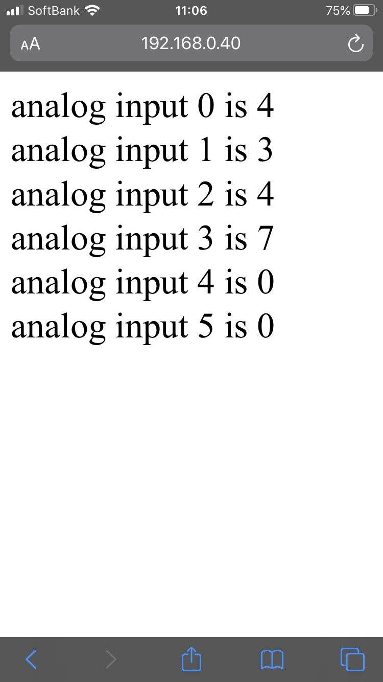 |
| BarometricPressureWebServer | The temperature and barometric pressure values acquired from the barometric pressure sensor by applying “WebServer” are displayed on the web browser. |
| UDPSendReceiveString | Set the IP address in advance. The other side uses Processing to communicate via UDP. Press Key on Processing to send “Hello World” to Spresense. When Spresense receives it, it returns “acknowledge” to the Processing side. |
| TelnetClient | Set the IP address and server address in advance. Spresense becomes the client side and connects to the server on port 10002. Send the characters entered in the serial monitor to the server side. |
So far, it’s like a normal Arduino compatible board that runs Ethernet, but what’s great about Spresense is that it has a multi-core environment. You can easily offload network processing by running the Ethernet library on a separate core. I would like to take on challenges in the future, such as network communication with the sub-core while moving the audio of the main core, or connecting the network with the sub-core while moving the camera board with the main core.
COMMENTS