ABSTRACT
Microgrid is a localized power network of connected loads and energy distribution sources which may operate autonomously with respect to the main central grid. Conventional protection schemes are not suitable for grid-connected and islanded modes of operation of microgrid. This paper proposes an adaptive protection center (APC) which is capable of real-time monitoring of the microgrid, fault identification and graph algorithms aided shortest path identification for fault clearance. The Internet of Things (IOT) based APC is capable of displaying system status and load characteristics in a remote system. The proposed APC is validated and tested for functionality on the hardware prototype of 8-bus microgrid network.
INTRODUCTION
Microgrid is a localized power network of connected loads and energy distribution sources which may operate autonomously with respect to the main central grid . Conventional power stations are centralized and often require electricity to be transmitted over long distances whereas microgrids are localized small-scale grids. These networks act as individual controllable units which have their own distribution generators (DG) and loads . These networks may act as individual controllable units which have their own distribution generators (DG) and loads.
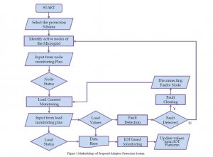
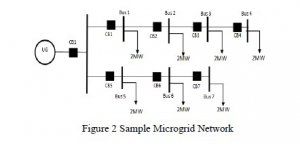
This paper presents an adaptive protection scheme for an eight-bus microgrid network by realizing a microgrid protection center (MPC) which is capable of identifying the fault location and fault clearance. The status of the system is continuously monitored by a remote monitoring system via IOT, which displays the real time current values of the buses. It also does fault detection and rectification in the microgrid system. It employs Graph Theory Algorithms at MPC to find the shortest path from the faulted point to its nearest operating source. The system status and load characteristics displayed on a remote device with the help of IOT.
IOT BASED MICROGRID PROTECTION SYSTEM
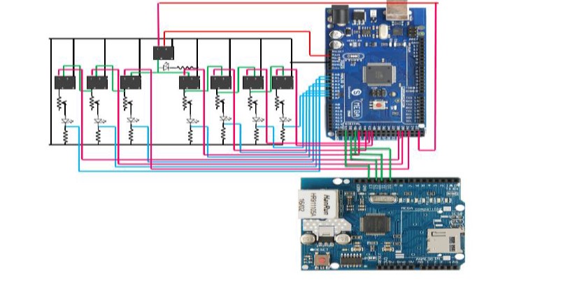
HADRWARE SETUP
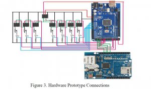
5V relays are used. The pin connections are shown in the Figure 3.
- The load is connected to the NO Contact of the relay. In normal operating conditions, the relay is activated by initializing a control signal in the code (from the MPC) and the load is connected to the grid.
- The signal is sent by the MPC to Pin 2 which is connected to the relay’s control coil. When the MPC detects a fault, another signal is sent to the control pin and the control coil de-energizes the electromagnet which open circuits the load circuit, thus restricting current flow in the load branch.
- The load branch consists of a 1KΩ variable resistive load, an LED and a fixed load of 220Ω. The analog pins of the Arduino are connected to the fixed loads. These connections enable the measurement of the voltage equivalent of current flowing through the fixed loads. These values are used in by the MPC for fault detection.
- The Digital pins of the Arduino are connected to Pin 1 of the relays. Two digital pins are connected to each relay, one for sensing the status of the relay and another for controlling the relay. The sensing pin and monitoring/control pin are connected appropriately. The Ethernet shield (W5100) module is mounted on the Arduino board with Supply and ground connections. The pin connections for the Ethernet shield module are done
IOT Implementation
Once the Ethernet shield is setup and bridged to the internet connection, we can setup the IOT platform. (Cayenne has been used for IOT implementation for this project)
1. Signup and login to the Cayenne platform.
2. From the list of devices, select Arduino.
3. From the list of supported Arduino boards, select the type. From the drop down menu, select the module that provides internet connectivity (Ethernet Shield W5100 in this case).
4. Click on sketch, it will generate a sketch file which will act as the base code to connect the Arduino to the platform. Dump this code on the Arduino processor using Arduino IDE and wait until the connection is established. Connection establishment sequence can be observed in the serial monitor of the Arduino IDE.
5. Once the connection is set up the following display appears and user can select the elements and widgets for their application specific dashboard
Once the device is connected to the Cayenne platform, the remote monitoring dashboard is designed.
1. From the list of widgets and components available on the home screen, select custom widgets (These are widgets that are configured by the user)
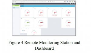
2. For the load current monitoring, gauge display widget is used. In order to setup the widget, the following parameters as depicted in Figure 4 should be set.
3. Click on the ‘Add Widget’ button and the widget will be added to the application dashboard.
4. After adding all the elements to the dashboard, it appears as in Figure 4.
Figure 4 Remote Monitoring Station and Dashboard
RESULTS
Remote monitoring system displays the load parameters. Color codes for different levels of operation are as indicated below:
Red – bus operating in danger zone
Yellow – Moderate zone, current near permissible limit
Green – normal operating zone
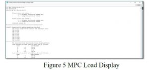
Figure 5 shows the system status and load characteristics as the load is displayed on the Arduino IDE.
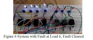
Case 1: Fault at Load 6
When an overcurrent fault is detected at load 6, a fault clearing sequence is initiated at the MPC and it disconnects the faulted node from the distribution grid. Figure 6 shows the system status after fault is cleared, disconnecting CB6 and thus loads 6 and 7 are inactive.
COMMENTS