1. W5500 module
1.1 Introduction of W5500 Ethernet Module
- D-W5500 EVB Ethernet module is an Ethernet module based on WIZnet W5500 chip, and it is a cost-effective Ethernet module. The W5500 is an all-hardware TCP/IP embedded Ethernet controller that provides a more recommended Internet connection solution for embedded systems.
- W5500 solidifies the TCP/IP protocol stack, 10/100Mbps Ethernet data link layer (MAC) and physical layer (PHY), enabling users to use a single chip to expand network connections in their applications. Built-in 32K bytes on-chip cache for Ethernet processing, and can use 8 hardware sockets for independent communication at the same time; SPI (peripheral ship interface) makes it easier to integrate with peripheral MCU, and W5500 uses high-efficiency SPI protocol to support 80MHz , so as to achieve high-speed network communication.
- The module also supports 3.3V or 5V power supply. When 5V is powered, it can also output 3.3V voltage, which is convenient for users to use in different microcontroller systems.
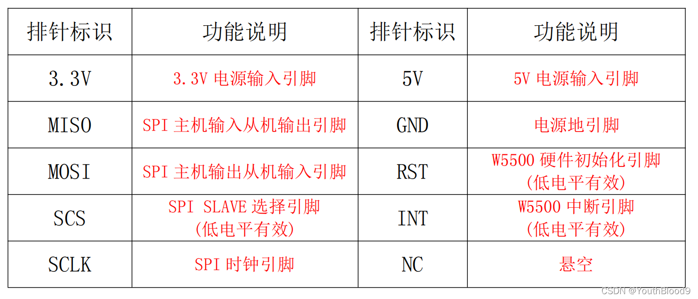
1.2 Module pin header function table
1.3 STM32 and W5500 line connection
PA3 -> W5500_RST
PA4 -> W5500_SCS
PA5 -> W5500_SCK
PA6 -> W5500_MISO
PA7 -> W5500_MOSI
1.4 Code + Debug
- Code:
Baidu network disk download link: https://pan.baidu.com/s/1_MhyxJTNH7_i5QbNNqb7jg
Extraction code: 1111 - Use the TCP&UDP test tool for debugging.
- Method (the following link is borrowed from the classmates)
resource sharing:
link: https://pan.baidu.com/s/1fiWWfmWQT9CNh4EimU-Igw
Extraction code: 1234
debugging tool Use the TCPUDPDebug102_Setup in the compressed package to install it yourself. - For the debugging process of the specific routine, please refer to the NiRen_W5500 module user manual (open with Adobe Reader).pdf file in the compressed package, and follow the steps.
- After everything is connected, after compiling and running in keil, open the debugging tool
1.5 Results
- In the debugging tool, the server mode can be:
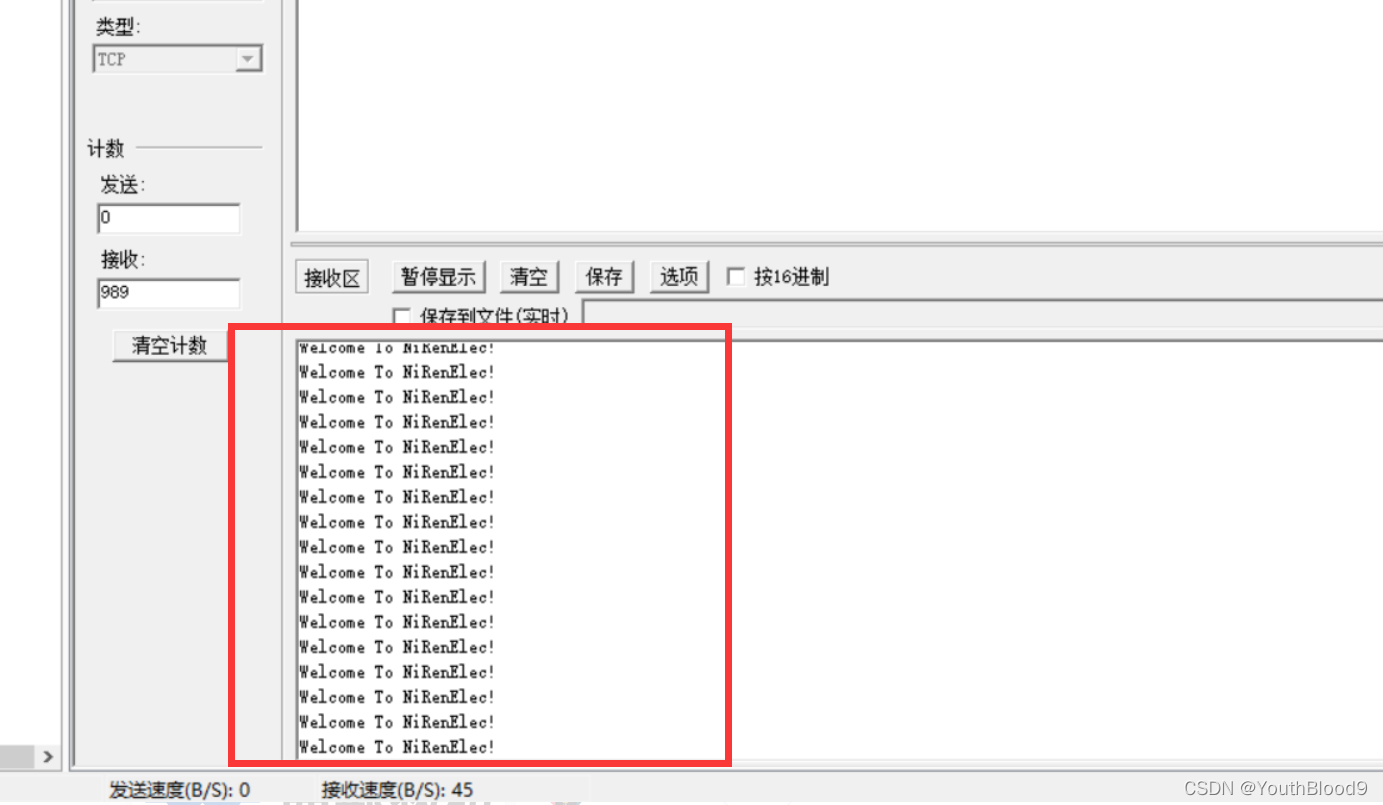
- the same as the client
2. STM32+W5500+ modbus protocol programming
2.1 modbus protocol
2.1.1 Principle of modbus protocol
Modbus protocol is a general communication protocol that has been widely used in today’s industrial control field. Through this protocol, controllers can communicate with each other or with other devices via a network such as Ethernet. The Modbus protocol uses the master-slave communication technology, that is, the master device actively queries and operates the slave device. Generally, the protocol used by the master device is called Modbus Master, and the protocol used by the slave device is called Modbus Slave. Typical master devices include industrial computers and industrial controllers; typical slave devices such as PLC programmable controllers.
Modbus communication physical interface can choose serial port (including RS232, RS485 and RS422), or Ethernet port. Its communication follows the following process:
The master sends a request to the
slave The slave analyzes and processes the master’s request, and then sends the result to the master
If there is any error, the slave will return an abnormal function code
The working mode of Modbus is request/response. In each communication, the master sends an instruction first, which can be broadcast or unicast to a specific slave; the slave responds to the instruction and responds as required, or reports an exception. When the master station does not send a request, the slave station will not send data by itself, and there is no direct communication between the slave station and the slave station.
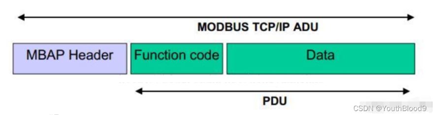
The Modbus protocol is an application layer (protocol layer) message transmission protocol. It defines a protocol data unit (PDU) that has nothing to do with the physical layer, that is, PDU = function code + data field, the function code is 1 byte, and the data field is uncertain.
The Modbus protocol can be applied to different types of buses or networks. Corresponding to different buses or networks, the Modbus protocol introduces some additional fields to map to application data units (ADUs), that is, ADU=additional fields+PDU, such as modbus tcp/ip—— ADU=MBAP+ADU.
2.1.2 Modbus communication mode
- Modbus three communication modes
Modbus has the following three communication modes:
(1), Ethernet: the corresponding communication mode is Modbus TCP/IP
(2), asynchronous serial transmission (various media such as wired RS-232-/422/ 485/; optical fiber, wireless, etc.): the corresponding communication mode is Modbus RTU or Modbus ASCII
(3), high-speed token passing network: the corresponding communication mode is Modbus PLUS
Modbus RTU and Modbus ASCII protocols are applied to serial link (RS232, RS485 , RS422), Modbus tcp/ip protocol is applied to the Ethernet link. - Transmission on the Modbus network The
standard Modbus port uses an RS-232C compatible serial interface, which defines the pins, cables, signal bits, transmission baud rate, and parity of the connection port. The controller can be networked directly or via Modem.
Controller communication uses a master/slave technique, ie only one device (the master) can initiate a transfer (query). Other devices (slaves) respond accordingly based on the data provided by the master query.
Typical master device: mainframe and programmable meter.
Typical slave device: programmable controller.
The master device can communicate with the slave devices individually, and can also communicate with all slave devices in a broadcast manner. If it communicates alone, the slave device returns a message as a response, and if it is queried by broadcast, it will not respond.
The Modbus protocol establishes the format of the master device query: device (or broadcast) address, function code, all data to be sent, and an error detection field.
The slave device response message is also composed of the Modbus protocol, including fields to confirm the action to be taken, any data to be returned, and an error detection field. If an error occurs during message reception, or the slave cannot execute its command, the slave will create an error message and send it in response. - Ethernet (modbus tcp/ip)
For Modbus TCP, the master is usually called Client and the slave is called Server; for Modbus RTU and Modbus ASCII, the master is Master and the slave is Slave.
The data frame of ModbusTCP can be divided into two parts: ADU=MBAP+PDU = MBAP + function code + data field, MBAP 7byte, function code 1byte, the data field is uncertain, determined by the specific function.

2.2 Code
- Initialize the slave network
void Load_Net_Parameters(void)
{
	Gateway_IP[0] = 192;//加载网关参数
	Gateway_IP[1] = 168;
	Gateway_IP[2] = 182;
	Gateway_IP[3] = 1;

	Sub_Mask[0]=255;//加载子网掩码
	Sub_Mask[1]=255;
	Sub_Mask[2]=255;
	Sub_Mask[3]=0;

	Phy_Addr[0]=0x0c;//加载物理地址
	Phy_Addr[1]=0x29;
	Phy_Addr[2]=0xab;
	Phy_Addr[3]=0x7c;
	Phy_Addr[4]=0x00;
	Phy_Addr[5]=0x01;

	IP_Addr[0]=192;//加载本机IP地址
	IP_Addr[1]=168;
	IP_Addr[2]=182;
	IP_Addr[3]=54;

	S0_Port[0] = 0x13;//加载端口0的端口号5000
	S0_Port[1] = 0x88;

S0_Mode=TCP_SERVER;//加载端口0的工作模式,TCP服务端模式- response function
void Process_Socket_Data(SOCKET s)
{
	int len;
	unsigned char msg[11]={0x00,0x00,0x00 ,0x00, 0x00, 0x05, 0x01, 0x03, 0x02, 0x00, 0x70};
	len=sizeof(msg);
	unsigned short size;
	size=Read_SOCK_Data_Buffer(s, Rx_Buffer);
	memcpy(Tx_Buffer, Rx_Buffer, size);

	//打印查询报文
	for (int j=0;j<size;j++){
		 printf("0x%02X ",Tx_Buffer[j]);
	}

	//写响应报文
	//检验码
	msg[0]=Tx_Buffer[0];
	msg[1]=Tx_Buffer[1];

	//协议
	msg[2]=0x00;
	msg[3]=0x00;

	//数据包长度
	msg[4]=0x00;
	msg[5]=0x05;

	//设备编号
	msg[6]=Tx_Buffer[6];
	//功能码
	msg[7]=Tx_Buffer[7];
	//数据长度
	msg[8]=0x02;

	//低八位
	msg[10]=data&0XFF;
	//高八位
	msg[9]=data>>8;

	memcpy(Tx_Buffer, msg, len);
	//发送响应报文
	Write_SOCK_Data_Buffer(0, Tx_Buffer, len);
	data++;
}
- 40
- 41
- 42
- 43
- 44
- The main function loops and waits for a connection
 while (1)
  {
		W5500_Socket_Set();//W5500端口初始化配置

		W5500_Interrupt_Process();//W5500中断处理程序框架

		if((S0_Data & S_RECEIVE) == S_RECEIVE)//如果Socket0接收到数据
		{
			S0_Data&=~S_RECEIVE;
			Process_Socket_Data(0);//W5500接收并发送接收到的数据
		}
		//从机状态标志
		HAL_GPIO_TogglePin(GPIOC,GPIO_PIN_13);

  }
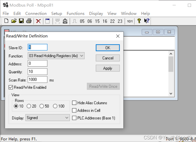
2.3 modbus poll to establish a connection


2.4 Results
- Serial display

For the complete code, please refer to the big guy:
https://gitee.com/zxsjunqi/keilcode/tree/master/Modbus_TCP-main/Modbus_TCP-main
COMMENTS