
1. Project overview
Smart home is an efficient, comfortable, safe and convenient home environment with home as a platform and architectural integration. It uses a series of high and new technologies such as home control bus, Internet, communication, artificial intelligence, single-chip microcomputer, and sensors to control home equipment, security management, life information and information management, home Internet communication and other common life elements that are closely related to our daily life. Carefully combined, it can highly improve the quality, convenience, safety, comfort and richness of our daily life. system. Relying on the platform of housing, it can scientifically manage all aspects of home life and make home life “smart”. The realization of this management process depends on key technologies such as computer technology, network technology, communication technology and integrated wiring technology. The purpose is to provide people with a more comfortable, safer and more convenient environment, so as to truly improve people’s quality of life and make people feel modern, fashionable and convenient life.
The smart home system is a system that realizes intelligent monitoring of household appliances, data acquisition equipment and security equipment. It includes functional modules such as intrusion alarm, gas detection, data acquisition and home appliance control. Among them, the gas detection and intrusion alarm modules with security functions are used to provide security for the family; the data acquisition module is used to collect physical quantities such as temperature and humidity, and send the data to the control module. The purpose of this module is to provide users with a comfortable, convenient and safe home environment.
2. Project structure
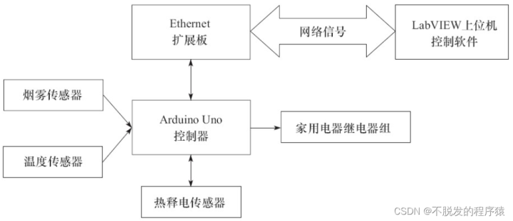
This blog post mainly introduces a remote smart home system based on TCP/IP network, using Arduino Uno controller as the lower computer, using LabVIEW as the remote monitoring software, the two communicate through the network.
For the download of project resources, please refer to: LabVIEW Arduino TCP/IP Remote Smart Home System [Practical Project]
3. Sensor selection
3.1. Gas sensor
In order to prevent the leakage of gas in the kitchen, causing gas poisoning and fire hazards, this system installs a gas sensor in the kitchen to detect whether there is natural gas leakage.
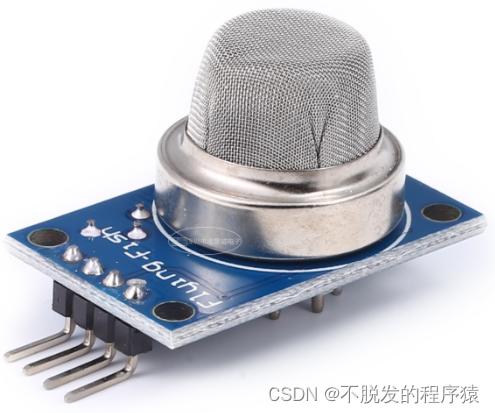
The gas sensor uses the MQ-X series gas sensor. This sensor adopts the MQ-X type gas sensor, which can detect the smoke and methane gas in the air very sensitively. Combined with buzzer module and relay module, it can produce smoke alarms, methane leakage alarms, automatic smoke exhaust fans and other products. It is an ideal sensor to make indoor air meet environmental protection standards.
MQ-2 is a gas-resistance-controlled gas sensor whose resistance value varies with the concentration (composition) of the gas to be measured. The gas sensor device is a kind of “gas-electric” sensor device, which converts the concentration (component) signal of the gas to be measured into a corresponding electrical signal, and the resistance value of the gas sensor device and the gas concentration are generally nonlinear. Gas detection in a fixed concentration range can be approximately considered to be linear, and detection within a certain concentration range is effective.
Gas sensors generally work under heating conditions, but the working temperature should not be too high (generally not more than 35°C), otherwise it will cause performance degradation and reduce gas sensitivity. After the device is placed for a period of time, when it is powered on again, the resistance value will first decrease and then increase again. After about 10 minutes of power-on (initial stabilization time), the resistance value can be stabilized to the corresponding resistance value of the atmosphere state. In order to avoid false alarms at the beginning of power-on, special attention should be paid to setting a delay time of ten minutes. The response time of the device is about 10 seconds, and the recovery time is about 30 to 60 seconds. When using, avoid oil immersion or grease pollution, and do not put the gas sensor in corrosive gas for a long time. When used for a long time, measures should be taken to prevent dust from clogging the stainless steel mesh.
The physical map of the MQ-2 gas sensor is shown in the following figure:
3.2, temperature sensor
DS18B20 is a digital single-bus intelligent temperature sensor from DALLAS Semiconductor, USA. Compared with traditional thermistors, it can directly read the measured temperature, and can realize 9~12-bit digital value reading through simple programming according to actual requirements. Way. Reading or writing information from the DS18B20 only requires one line (single bus) to read and write, and the bus itself can also supply power to the connected devices without additional power.
Extended Learning: LabVIEW Controls Arduino to Collect Multiple DS18B20 Temperature Values (Advanced Chapter-3)
3.3. Pyroelectric infrared sensor
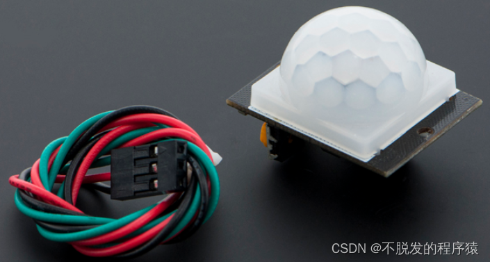
The pyroelectric infrared sensor is mainly made of a high pyroelectric coefficient material, such as lead titanate ceramics, lithium bicarbonate, and titanium triglyceride sulfate, etc. The detection element is 2mm × 1mm in size. One or two detection elements are installed in each detector, and the two detection elements are connected in series with opposite polarity to suppress the interference caused by the increase of its own temperature. The detected and received infrared radiation is converted into a weak voltage signal by the detection element, which is amplified by the field effect tube installed in the probe and then output to the outside. In order to improve the detection sensitivity of the detector and increase the detection distance, a Fresnel lens is generally installed in front of the detector. The lens is made of transparent plastic, and the upper and lower parts of the lens are divided into several equal parts. It is a lens with a special optical system, which cooperates with the amplifying circuit to amplify the signal by more than 70dB, so that the movements of people within 10 to 20 meters can be measured.
The window of the pyroelectric infrared sensor receives light, and the filter has an inhibitory effect on the white light signal in nature, so only the infrared signal of a specific wavelength can pass through the filter and irradiate on the pyroelectric element. After the pyroelectric element is illuminated, due to the different illumination on the upper and lower surfaces of the pyroelectric element, electrons are generated and a current is formed, so that the two black coatings generate different pyroelectricity, and the current passes through the field effect tube and amplifies the output voltage signal. .
Pyroelectric infrared sensors have the advantages of not emitting any type of radiation, low power consumption of the device, good concealment, and low price. The disadvantages are as follows:
1. Easily interfered by various heat sources and light sources;
2. The passive infrared penetration is poor, the infrared radiation of the human body is easily blocked, and it is not easy to be received by the probe;
3. When the ambient temperature is close to the human body temperature, the detection and sensitivity are obviously reduced, sometimes causing short-term failure.
3.4. Relay
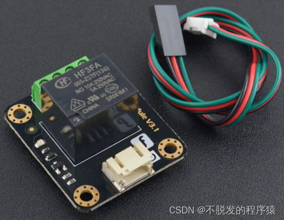
The relay is an electrical control device, when the change of the input quantity (excitation quantity) reaches the specified requirements, the controlled quantity will undergo a predetermined step change in the electrical output circuit. It has an interactive relationship between the control system (also known as the input loop) and the controlled system (also known as the output loop), and is usually used in automated control circuits. automatic switch”.
Electromagnetic relays are generally composed of iron cores, coils, armatures, contact reeds, etc. As long as a certain voltage is applied to both ends of the coil, a certain current will flow in the coil, resulting in an electromagnetic effect, and the armature will overcome the pulling force of the return spring and attract to the iron core under the action of electromagnetic attraction, thereby driving the armature. The moving contact and the static contact (normally open contact) are pulled together. When the coil is powered off, the electromagnetic suction also disappears, and the armature will return to its original position under the reaction force of the spring, so that the movable contact and the original static contact (normally closed contact) are released. In this way, the suction and release are achieved, so as to achieve the purpose of conducting and cutting off in the circuit. For the “normally open and normally closed” contacts of the relay, it can be distinguished as follows: the static contacts that are in the open state when the relay coil is not energized are called “normally open contacts”; the static contacts that are in the connected state are called “normally open contacts”. It is a “normally closed contact”.
4. Hardware environment
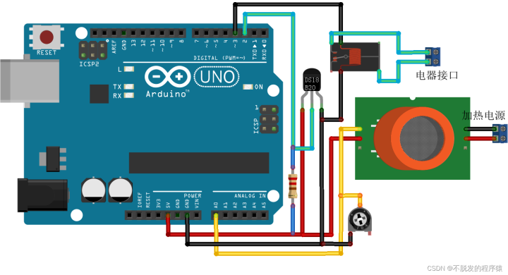
Connect the Vcc and GND of the DS18B20 temperature sensor to the +5V and GND of the Arduino Uno controller to supply power to the DS18B20, the DQ pin of the DS18B20 is connected to the digital pin D2 of the Arduino Uno controller, and a 4.7KΩ pull-up resistor , because the DQ pin of DS18B20 needs to add a pull-up resistor for normal operation.
Connect the two H pins of the MQ-2 gas sensor to the positive and negative poles of the heating power supply, and adjust the output +5V voltage of the power supply module; connect the A and B terminals to the +5V and analog inputs of the Arduino Uno controller respectively AO, and connect a load resistor in series between the B terminal and GND.
Connect the control terminals of the solid state relay module to the digital ports D3, D4, D5, D6, and GND on the Arduino Uno control board. Only one relay is shown on the hardware connection diagram, and the rest are similar.
Connect the VCC, OUT and GND of the pyroelectric infrared sensor to 5V, digital interface D7 and GND on the Arduino Uno control board respectively. It is not shown on the hardware connection diagram here.
Part of the hardware connection of the remote smart home system is shown in the following figure:
5. Arduino functional design
In the remote home monitoring system based on Arduino and LabVIEW, the Arduino Uno controller needs to complete the following functions:
1. Receive and judge commands through the W5100 network module, collect and transmit the data of temperature, gas concentration, and pyroelectric sensors, and upload them to the LabVIEW software through the W5100 network module;
2. Receive and judge commands through the W5100 network module, and control the opening and closing of multi-channel relay modules to control the closing and working of household appliances.
The program code of the Arduino controller of the remote smart home system is as follows:
6. LabVIEW functional design
The LabVIEW host computer part needs to complete the following functions:
1. When the switch of the household appliance is triggered, the state switching command of the specified household appliance is sent to the Arduino controller of the lower computer. The Arduino controller reads the command of the upper computer through the W5100 module, and then controls the closing and opening of the solid state relay module to achieve Specify the on/off of household appliances;
2. When there is no operation on the front panel and the timeout is 1 second, the read commands of temperature, gas concentration and pyroelectric sensor are sent to the Arduino controller of the upper computer in turn. The Arduino controller reads the commands of the upper computer through the W5100 module, and reads all The required data is uploaded to the LabVIEW host computer software through the W5100 module for display.
6.1. Front panel design
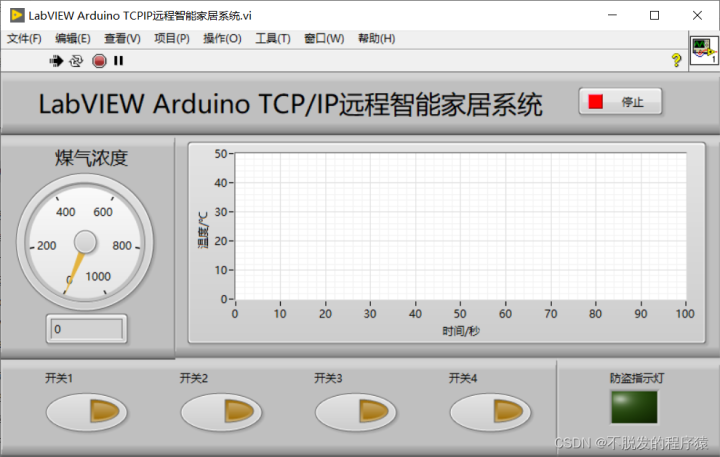
The front panel of LabVIEW is divided into instrument panel display, waveform display, and electrical switches. The instrument panel is used to display the current gas concentration, the waveform display is used to display the trend of temperature changes, and the electrical switch is used to control various electrical appliances. working status. Meanwhile, the anti-theft indicator in the lower right corner shows the status of the pyroelectric sensor.
The front panel of the LabVIEW host computer of the remote home monitoring system is shown in the figure below:
6.2, block diagram design
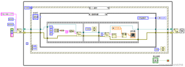
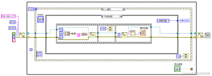
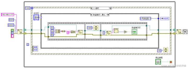
The event structure + timeout structure is used to realize the two parts of measurement and control. In the measurement, the condition structure + enumerated state machine is used to realize the reading of temperature, gas concentration and pyroelectric sensor data, and the measurement program is divided into 3 states : Temperature measurement, gas detection and anti-theft indication.
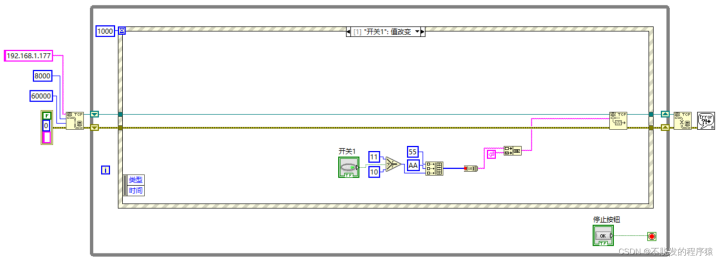
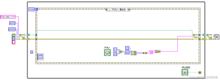
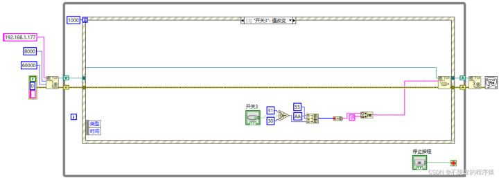
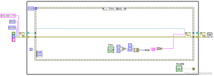
In order to better realize communication, the following communication protocol is formulated: frame header + opcode. 0x55AA is the frame header, opcode 0x80 is pyroelectric sensor data acquisition, 0x81 is gas concentration acquisition, 0x82 is temperature acquisition, 0x11 is the first relay closed, 0x10 is the first relay disconnected, and 0x21 is the second The relay is closed, 0x20 is the second relay is open, 0x31 is the third relay is closed, 0x30 is the third relay is open, 0x41 is the fourth relay is closed, and 0x40 is the fourth relay is open.
The block diagram of the timeout part of the LabVIEW host computer is as follows:
The block diagram of the value change event for the four switches is shown below:
After programming the program to the Arduino Uno controller, connect the W5100 network module and the computer to different LAN ports of the same router with a network cable, and use the “Highlight Execute Code” in the LabVIEW program to observe whether the TCP initialization is successful. If not, restart the Arduino Uno controller.
In addition, the router on the side of the Arduino Uno controller needs to be directly connected to the public network, not as a secondary router, and the router needs to be set up so that the network IP address of the Arduino Uno controller can be detected by the remote LabVIEW software. Since different routers have different setting methods, please search the Internet for specific router setting methods.
For the download of project resources, please refer to: LabVIEW Arduino TCP/IP Remote Smart Home System [Practical Project]
COMMENTS