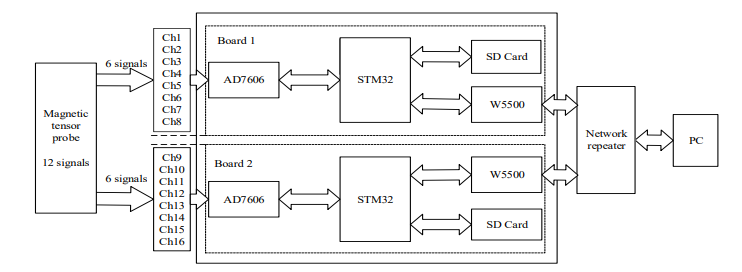
The AD7606 data acquisition, It uses internal precision reference voltage[5] and is connected to STM32 through SPI interface . When the DB15 pin is grounded,
the data transmission mode is SPI mode. BUSY pin connected to PB5 pin was set as an external
interrupt pin, and RST pin was connected to PB6 as the reset pin. The acquisition trigger signal is
connected to the CVA and CVB for the start conversion pin. In order to ensure the equal interval of
data collection, the PWM working mode of MCU timer is used to generate the start signal of A/D.
When the trigger signal is received, AD7606 begins to perform A/D conversion. After the conversion, the BUSY pin triggers the MCU interrupt, then it can read the data in the interrupt handler
The network communication circuit’s control unit is W5500. It connects to STM32 via SPI interface. W5500 supports eight hardware sockets for independent
communication. This network acquisition card uses two separate sockets for data port and command
port respectively. The two ports work independently, which is helpful to the stable operation of
network transmission. In order to make it easy for the client to recognize when it receives data, eight
fixed values are added to the header of the data package. After receiving the data, the client verifies the data packet header, then processes, displays and stores the data.
SD card is used for data storage and used the FATFS file system. During the working process of
MSDAS, the AD7606 and W5500’s data communication is faster than that of SD card. So the overall operating speed is limited by the storage speed of the SD card. So the SDIO interface is adopted. Compared with SPI mode, the speed of SDIO bus is faster. Then the overall
operating efficiency is improved.
COMMENTS