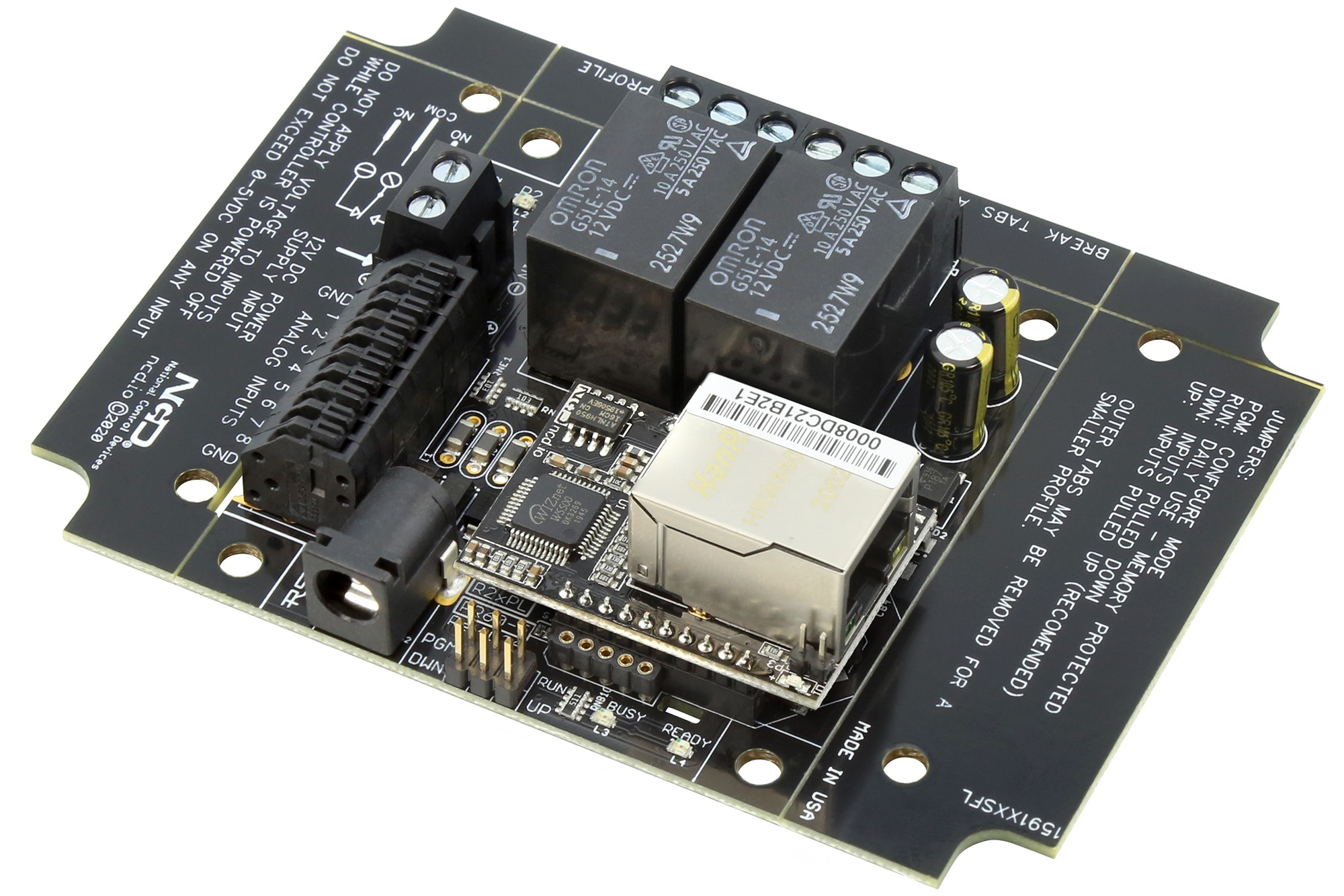
2-Channel SPDT Relay Controller with 8-Channel ADC
This ProXR Lite relay controller is capable of switching 4 on-board SPDT relays, each with 5 or 10 Amps of current, customized at the time of ordering. Each SPDT relay includes 3 screw terminals for normally open, common, and normally closed contact closure relay output connectivity. This controller features a modular communications interface, capable of accepting USB, RS-232, Ethernet, WiFi, Bluetooth, Industrial Wireless communication modules, and more. On-Board Analog to Digital Converters allow monitoring of 8 inputs at 8 or 10-Bit resolution. Analog inputs are ideal for connecting external sensors, or connect buttons and switches to the inputs and configure the controller to manually control relays when buttons are pressed. Turn relays on or off, toggle the state of a relay, or trigger relay flashers all from external switches.
SPDT Relay Controller Specifications
This table covers all NCD SPDT Relay Controllers. All ratings assume 12VDC operation at 70°F (21°C). Please note that most ratings are estimated and may be subject to periodic revision. Some ratings represent stock controller settings without performance enhancement optimizations. The estimated processing time can be impacted by background services and choice of commands. Standby power consumption assume no communications module is installed and no relays are active on the controller. Please add the power consumption of the activated relays and communications module to obtain a better estimation of power consumption.
Communication Module Specifications
This table covers all NCD Communication Modules. While NCD communication modules operate at 3.3VDC, the ratings below highlight the effect they will have on the master controller operating at 12VDC at 70°F (21°C). Maximum ratings should be used for power budget planning purposes and may reflect short term absolute maximum peak current consumption. Some ratings are estimated and subject to periodic revision.
AD8 Analog Input Usage Notice
Analog Inputs should not have a voltage present when powered down. Use a 220 Ohm current limiting resistor on each input to prevent damage to the controller if voltage will be present on the analog input when this controller is powered down. Do not exceed 0 to 5VDC on any analog input or the on-board CPU will be damaged. Most analog inputs include a 10K Pull Up/Down resistor to help keep the inputs quiet when not in use. This 10K resistor may slightly bias the readings of some sensors.
COMMENTS