INTRODUCTION
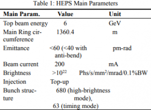
An ultra-low emittance and high brightness 4th generation synchrotron light source, the High Energy Photon Source (HEPS) designed by the Institute of High Energy Physics (IHEP), has started its construction since June 2019. The main parameters for HEPS are listed in Table 1which contains many challenging goals. It is necessary to have accurate installation, state-of-art equipment and high precision controls with high reliability. The control systems and related computing facilities are extremely important for the HEPS which includes not only traditional
control architecture design but also quality control for the project. Also, the HEPS control systems support not only the accelerator but also 14 beamlines which will be constructed at the same time. To build such a complex accelerator-based user facility, it is necessary to have an overall complete design for the control systems.
The basic design principles for HEPS Control Systems are listed below:
• Top-down architecture design: understanding the big picture
• Distributed control systems
• Integrated development tools (GUI code editors, repository management…) for higher software quality
• Choosing advanced yet matured technologies
• Using industrial standards, choosing commercially available products first for lowering costs
• Considering expandability at design, balancing the price and performance while satisfying physics requirements
• Collaborating with other accelerator projects
• Possible commercialization for R&D results
DATABASES
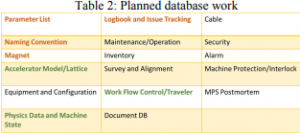
Accelerator generated data, from design to operation, should be captured and saved systematically as much as possible. Furthermore, applications to utilize the saved data should be developed as well. However, due to the large data-base scale and tremendous amount of work, it is necessary to divide the entire database into many nearly independent sub-database modules and connect them via API (Application Programming Interface) or services. Optionally, one can join some sub-databases together with minor modifications in the schemas. This way the database module development work can be shared independently by many institutes and also avoid overwhelming complexity for a single monolithic database.
ACCELERATOR CONTROL
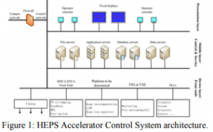
HEPS accelerator controls is EPICS-based, distributed systems. The system design principles are applying industrial standards, global timing system for both accelerator and experiments, and modularized subsystems for easy upgrade and maintenance. The overall accelerator control system architecture is shown in Fig. 1 with typical Device,
Middle, and Presentation layers. The Device layer provides the control interface, such as μTCA, PXI or PLC, to devices. The Middle layer performs data assembly and persistence, and online analysis computation. Details for some critical control system components are described below. Presently HEPS selects the latest EPICS version 3 as the control system platform. The EPICS-based device control will choose mostly industrial standard with EPICS driver support. Besides fast communication networks for global timing system, fast machine protection system, and fast orbit (FOFB) feedback system, the standard communication is through EPICS Channel Access (CA) protocol.
Magnet Power Supply Control
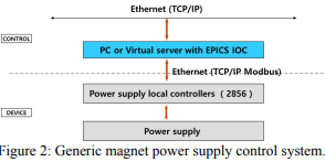
HEPS accelerator contains about 2500 magnets which are powered by over 2800 power supplies. For power supplies other than those for the Storage Ring FOFB correctors are through Ethernet interface for data transmission. The generic magnet power supply control system is shown in Fig. 2, which has an Altera Cyclone 5 Field Programmable Gate Array (FPGA) chip and W5500 Ethernet interface.
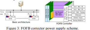
Because the Storage Ring FOFB correctors are serves for not only for FOFB but also slow correction, the power supply controller for these correctors have additional optical fiber interface as shown in Fig. 3. The “slow” part of the FOFB corrector control is through the basic architecture shown in the left diagram of Fig. 3, and the “fast” part of the corrector is controlled by the right side of the interface in Fig.3.
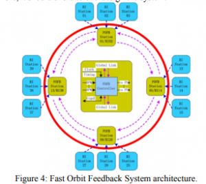
Fast Orbit Feedback System
For the extremely low emittance requirement, an FOFB system is required to correct orbit oscillations caused by ground vibration, magnet power supply ripple and any other possible causes. The orbit stability is to first suppress any known source causing beam oscillation. The FOFB is the last line of defense for beam bunch oscillation, therefore, it should avoid to overdesign the system.
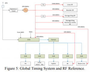
Global Timing System
HEPS Timing system is responsible for not only the accelerator but also all the beamlines and experiment stations. The overall timing system diagram which includes a distributed event trigger system and a RF reference system is shown in Fig. 5. The red lines in Fig. 5 represents the RF reference lines and the blue lines are event trigger distributions. The main requirements for the HEPS Global Timing System are RF phase stability less than ±0.1 degree peak-to-peak in the Storage Ring, the bottom width of injection kicker pulse less than 12ns, and the phases of reference line clock and event timing system recoverable after power drop. The master clock is running at 499.8 MHz which can be easily up-scaled to 2998.8 MHz for the Linac or downscaled to 166 MHz for the Storage Ring.
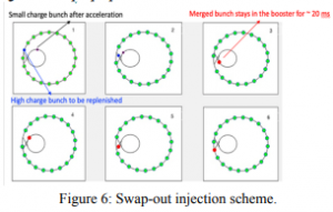
HEPS needs to deal with very small dynamic aperture for minimizing perturbations to user experiments, and recharging and re-energizing bunches in the Storage Ring, a complicated swap-out injection as shown in Fig. 6 is designed for top-up operation.
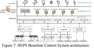
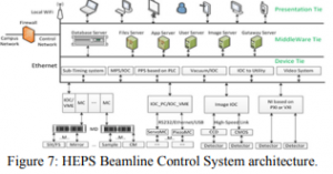
BEAMLINE CONTROL
As shown in Fig. 7, HEPS beamline control system architecture is similar to the accelerator controls’. For better manpower resources sharing, the HEPS optical beamline control is also handled by many accelerator controls experts. Also, it is not practical to have each beamline possessing its own database experts and handle all computing needs, for example. Many tools and platforms built for the accelerator can also be shared by the beamlines. Standards like naming conventions and EPICS supported devices are also shared.
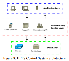
HIGH-LEVEL SOFTWARE
High-level applications are the tools for operating the HEPS properly. As shown in Fig. 8, the overall high-level application architecture and application flow can be divided into three layers: data, software API or services, and application GUI. For better software architecture, reusability, and easy-to-program purposes, same functions appear in multiple applications should be converted to either regular callable APIs or service APIs in the middle layer. Furthermore, due to the nature of the functions, it is better to separate them in three groups so they don’t mixed together and lose the flexibility: control system API, physics and general-purpose API, and ML API. The three API groups are also released independently as separate software packages. Details for these APIs will be de-scribed below.
CONCLUSION
The HEPS control systems have been initially designed and a few tasks have been started. Modern technologies will be applied to the actual implementations as further detailed design work done. For the software shareable between accelerators and optical beamlines as well as experiment stations, collaborations are formed. Starting from project supports like databases and project management tools, the controls team is also design and development work in many areas.
COMMENTS