components
Hardware Components
Ethernet shield w5100
X 1
Arduino Mega 2560
X 1
Actuators
X 1
Router
X 1
Arduino Nano
X 1
Farm Sensors
X 1
details
I. INTRODUCTION
There has been strong relationship between humans and animals throughout the centuries. We depend on animals in many aspects of life such as sports, food, clothes and other product that support and facilitate our living. Therefore a good care of animals is very important. The livestock industry could greatly be benefitted from a sophisticated system capable of
continuously monitoring the health of animals, aggregating the data and reporting the obtained results to owners and regional [1]. The term Internet of Things (IoT) was first defined by Kevin Ashton in 1999 [2]. It is a new paradigm about the ability of connected devices to sense and gather data, and then share that data using the Internet facility so that it can be processed and utilized to fulfill common goals [3]. IoT refers to a technology that tells that in near future billions of devices will have intent connectivity and can be accessed from anywhere in the world. According to [4], there can be many IoT enabled applications such as smart parking, smart animal farm, smart waste management system etc Stock theft has been a main problem in the agricultural sector in many countries around the world and threatens both commercial and the emerging farming sectors. In [5] authors carry out investigation about cow behavior modeling using global positioning wireless nodes to acquire the probable position of a cow. A WSN node was designed to sense the speed and position of a cow to determine the presence of a thief. The position and the speed of the cow were collected for analysis purpose.
II. SYSTEM DESIGN
We discuss complete system design in two main parts; i.e. hardware design and software design
A. Hardware Description
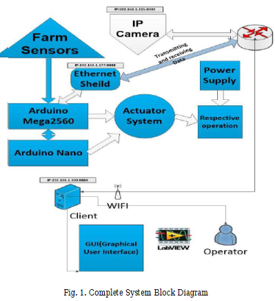
The designed system mainly consists of two modules; embedded system module and Ethernet communication module. The first module contains Water level sensor, Biogas Sensor, temperature and humidity sensor, fire sensor and two microcontrollers (i.e. Arduino mega and Arduino Uno) which are placed in the animal farm to sense the system parameters.
The data is transmitted by Ethernet shield through WIFI using UDP. The embedded system module acquires information of the animal farm and maintains the record and performs respective function in real time. It has two modes of operation; i.e. automatic mode and manual mode. If the system is in automatic mode, the system operates according to the
programmed threshold values and keeps on giving feedback through GUI on Certain IP. Moreover, if the System is in manual mode it is controlled manually using switches in GUI. This smart animal farm consists of subsystems which are BioGas Control System, Feed Control System, Incubator Control system, IP Camera, Fire Detecting System, and Water Control System. Complete system is shown in Fig. 1

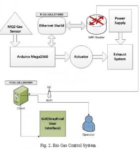
a) Bio Gas Control System
Animals’ waste causes biogas emission which can be harmful to them. To get rid of it, we have designed an exhaust system which will let the bio gas emit out from the farm. Exhaust system having fan which turns on when bio gas level is detected using the gas sensor. It works automatically if the system is in automatic mode, however one can turn it on/off manually by transmitting control signal from GUI to processing unit using WIFI. The system block diagram is shown in Fig. 2
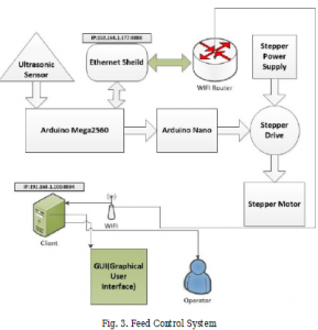
b) Feed Control System
Feed control system consists of hopper storage and feed storage. The hopper storage have a valve which is turned on using stepper motor and the feed storage having ultrasonic sensor which is used to sense the level of feed. As the level of feed decreases the hoper valve turns on so that feed can be filled. The system block diagram is shown in Fig. 3.
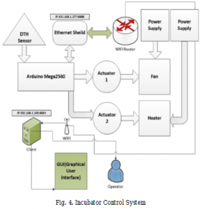
c) Incubator Control System
Incubator box consists of a temperature Sensor, a humidity sensor, a heater, and a fan. Sensors sense the humidity and temperature of the incubator according to predefined conditions
and subsequently either heater or fan is turned on or off. The system block diagram is shown in Fig. 4.
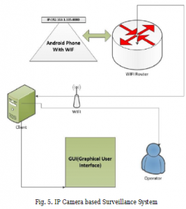
d) IP Camera based Surveillance System
We have used an Android cell phone as an IP camera using application “IP Cam”. This application is connected with same WIFI router to have IoT based system. Fig. 5 shows block diagram of IP camera based surveillance system.
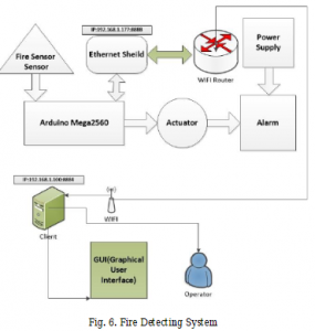
e) Fire Detecting System
Fire detecting system consists of fire sensor module and an alarm. When a fire sensor module detects the fire in the system it turns on alarm if the System is in automatic mode so one can rescue animals. Fire sensor also gives an indication to GUI through WIFI. The alarm buzzer can be controlled manually as well in an emergency condition. Block diagram of Fire Detecting System is shown in Fig. 6.
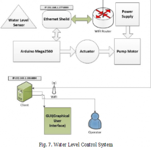
f) Water Level Control System
Water level control system has water level sensor and a waterpump. Water level sensor senses the level of the water in the Proceedings of the 10th INDIACom; INDIACom-2016 3rd 2016 International Conference on “Computing for Sustainable Global Development”, 16th – 18th March, 2016
B. System Software
The monitoring and controlling takes place by receiving and transmitting the data over a specific IP address and port address using User Datagram Protocol (UDP). LabVIEW software is
used for making a GUI of an IoT enabled smart animal farm. LabVIEW provides a very good platform for any measurement or control system. GUI consist of switches and different
measuring scales that keep on receiving data from the environment using WIFI
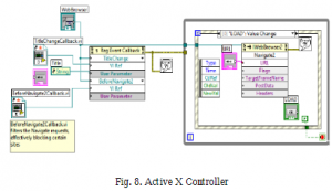
a) Active X Controller
ActiveX Event callback for IE is used in GUI which displays an IP Camera result of the video feedback acquired from farm [7]. LabVIEW block diagram is shown in Fig. 8.
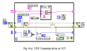
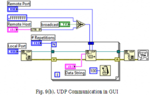
b) UDP Communication in GUI
User Datagram Protocol (UDP) provides a means for communicating short packets of data [8]. The Data is sent in multiple packets and these packets arrive at the destination in the order they were sent. The receiving data over UDP gets concatenated and is shown in the panels of GUI of the system i.e. humidity, temperature. LabVIEW block diagram of UDP communication in GUI is shown Fig. 9 (a) and Fig. 9 (b)
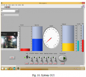
c) GUI Representation
GUI is having an IP Camera panel, vertical progress bar to indicate fire, vertical tank bar to indicate water level in tank, a numeric gauge to indicate bio-gas, a vertical yellow tank to indicate feed in tank, a humidity bar and a thermometer bar to indicate humidity and temperature respectively. Complete system of animal farm will keep on giving readings of the environment by using sensors to a processing unit. Processing unit will have certain IP and port address (ie.XXX.XXX.XXX.XXX:8888). IP camera has a certain IP and port address (ie.XXX.XXX.XXX.XXX:8888) that is connected to a central router which transmits data to a desired IP and port by which this system can be monitored and controlled
III. SYSTEM OPERATION
The complete system operation is shown in system flowchart in Fig. 11
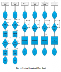
The complete system operates as described below:
If the biogas indication is less than threshold value it will not turn on exhaust system. If it becomes more than a threshold value it will start an exhaust system.
If the feed in the container is less than a threshold value or a certain quantity then system turns on the feed valve to maintain up to a specified level.
If the temperature and humidity of the incubator is less than a threshold value, the system turns on heater. Otherwise fan is used to maintain the humidity.
IP camera keeps providing a continuous video feed to the GUI panel.
If the fire sensor value goes below the threshold value, system turns on an alarm.
Finally, if the water level becomes below the threshold value, the system turns on the water pump.
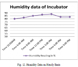
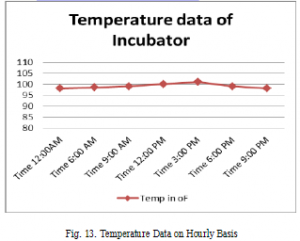
IV. RESULTS
Results related to humidity, and temperatures are shown hourly basis in Fig. 12 and Fig. 13 respectively. The humidity of the system is low in day time hours as shown in Fig. 12. It rises especially in evening hours. The results reveal that it can be maintained using this smart system.
V. CONCLUSION
In this paper we have designed an IoT enabled smart animal farm. This is a cost efficient system and is built with a cost of USD300. It continuously monitors the physical parameters of an animal farm. It can be controlled manually as well as automatically. This kind of system is suitable for any kind of animal farm with little modifications.
COMMENTS