Introduction
With the rapid development of engineering machinery, load sensitive phenomenon has been brought in the engineering machinery dynamical system. It is widely used in engineering machinery due to its high energy efficiency. Nowadays, domestic scholars have designed a lot of multi-way valve systems, but the hydraulic test system based on the trait of load-sensitive multi-way valve and the accomplishment of the relevant performance tests is rarely reported. For this reason, it is necessary to realize the traits of a load-sensitive multi-way valve which is applicable for agricultural machinery operation and invent a set of testing system for experimenting on the load-sensitive multi-way valve.
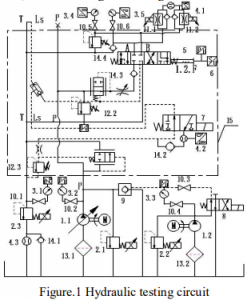
The Design of Load-sensitive Multi-way Valve Hydraulic System Brief Introduction of the Tested Valve. Load-sensitive multi-way valve is a small hydraulic system combined with various kinds of valves. It is always composed of oil inlet connection, working connection and terminal connection. The number of working connection is customized, and it is determined by the needed external load as the engineering machinery real working[3].
Shown in picture 1, No.15 is a load-sensitive multi-way valve used on an agricultural machinery with one working connection. Its oil inlet connection includes of manual directional valve, shuttle valve and pressure compensation valve. The pressure compensation valve combines with the instant sectional area of the pilot valve in the directional control valve to regulate the flow.
The Design of Hydraulic Testing Loop. During the design of load-sensitive multi-way valve testing system, we considered the tested valve’s self-load-sensitive feature and the essence of
multi-way. According to the B/T8729-2013 hydraulic multi-way directional valve machinery industrial standard and relevant industrial standards, the test theory figure shown in Fig.1 was designed. Proportional overflow valve is used to set up the pressure of the whole system in order to reach the testing requirement[4][5]. Nevertheless the pressure sensor and the flow sensor can choose different measuring range according to the actual situation. In view of the smaller flow of the load-sensitive port LS, a flow sensor is chosen, which has a higher precision. For this reason, ZHM 01/21)*,with the measuring range of 0.02-3L/min and the measurement accuracy of ±0.5%, produced by Shanghai Kem observation and control technology limited company is chosen to use.
Brief Introduction of a Main Test Program. A main program testing method according to the hydraulic testing loop is introduced as follows, shown in Fig.1. Fretting behavior test: adjusting safety valve of the tested valve to nominal pressure and turn off all overload valves. ○1 Pressure fretting behavior from P to T: plugging the tested valve oil port B and A, letting nominal flow rate going through port P, the slide valves move from the neutral position to every commutation position slowly. At this time the relevant pressure parameter varying
with the movement of oil port P is measured.
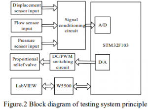
Design of the Testing Hardware Part
The test system is controlled by upper computer and lower computer. The system operation is shown in Figure 2. Signals of the tested system such as flux, displacement, pressure, etc. are measured by relevant sensors. Sensors’ data go into STM32F103 after being voltage-sampled and converted by signal conditioning circuit and A/D conversion module. Afterwards the digital signals converted will be computed by specific control algorithm in the software. The result outputs to the W5500 net card module, which brings with external TCP/IP protocol, to achieve the data transmission to industrial personal computer (IPC). At the same time, the overflow valve can be adjusted by PWM signal, and the result will be sent to IPC. When the testing system pressure or flow changes, IPC with LabVIEW software will send new signals to W5500 and then delivered to STM32F103, and to realize the signal control and feedback consequently.
Design of the Testing Software Part
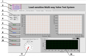
The higher computer software of the testing system is written by LabVIEW. In consider of the limitation of laboratory testing condition, the testing projects mainly include safety valve transient response test, steady state test, fretting behavior test, internal leakage and back pressure test. Steady state test, for instance, as is shown in Figure 4, is the operation interface of steady state test. All of the operation interface meets with the functions mainly about: (1) store the essential information such as the name of operating personnel and time. (2) complete the transient response
test, steady state test and operating force test of load-sensitive multi-way valve.(3) users operate in real time and send commands for lower computer to control the proportional overflow valve.(4) collect data and realize the displaying, saving and printing out in LabVIEW interface, as shown in Fig.4. The program is shown in figure 5.
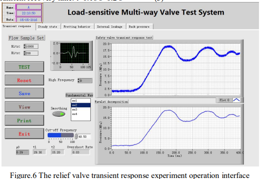
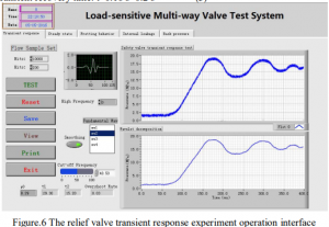
Safety Valve Transient Response Test
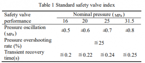
Since testing projects are too many, this article just introduces the safety valve transient response test and its test result of load-sensitive multi-way valve. The specific methods and procedures of the experiment: first, turn off overflow valve2.1, plug oil port A and B of the tested valve. And then put slide valve at commutation position, adjust the safety valve to 16MPa, turn on pump 1.2 and adjust proportional overflow valve 2.2 and control the pressure to speed up the operation of discontinuity loading valve.
Conclusion
The article introduces a special load-sensitive multi-way valve for an agricultural machinery, designs the diagram of the load-sensitive multi-way valve principle, writes the testing software
based on LabVIEW and the hardware testing system with STM32 and W5500 as the core. It can not only shorten the development period of the system and save the cost. After that, it introduces the safety valve transient response test of the tested valve and gets the experiment data to compare with the standard data. The final testing result shows that this testing system is reliable and provides a reference for the research of load-sensitive multi-way valve testing system.
COMMENTS