Introduction
Potential risks exist in places like power stations whose internal structure is complex, it’s high time that we insured its safe and reliable operation. Once fire occurs in power station, the consequence it might bring is serious. Therefore, strict requirements for the operators’ field operation are put forward and there is no room for error. The operators at post should receive high-level education and training, have superior safety consciousness and conditioned reflex to the fire alarm. For these reasons, a fire alarm simulation training system seems to be of great significance.
System Structure and Main Function
A. System Structure.
The fire-fighting equipment manual-control-pad simulation system is mainly consisted of the following parts: TMS320F28335, the W5300 Ethernet interface, the LED module, the keyboard module and the upper computer. Its system structure figure is shown as Fig.1

B. Main Function.
When the operator receives fire alarm signals or trouble signals of a specific spot, he is supposed to start the corresponding fire fighting equipment or solve the trouble through the manual control pad. The manual control pad is consisted of 16 keys and 24 LEDs which are divided into 8 groups, it’s to say.
Design of System Hardware
A. Design of W5300 Ethernet Interface.
W5300 is a chip with integration of 10/100M Ethernet Controller, MAC and TCP/IP protocol stack. It’s convenient, steady, and is widely used in the high-performance, low cost embedded fields. W5300 is easy to be connected with the CPU by the Bus Interface in direct access mode or indirect access mode. The load of CPU decreases for the reason of W5300’s ability to process communication protocol in it, therefore, the performance of CPU improves significantly. The schematic diagram of the hardware interface betweenW5300 and TMS320F28335 is shown in Fig2.

B. Design of Keys and LEDs Modules
24 LEDs are divided into three groups. With the addition of current-limiting resistances, 8 LEDs with common anode in each group are connected to the GIOPs of TMS320F28335 through a bi-directional tri-state data buffer. 74HC245 is an eight-channel tri-state data buffer with controlled direction. Its main function is to realize the two-way asynchronous communication of the data bus. Data buffer is often applied to protect the fragile main control chip.16 keys are connected between the power and ground through current-limiting resistances.
Design of System Software
A. Design of Main Program
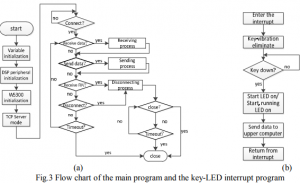
System software includes W5300 Ethernet Interface program and key-LED interrupt program. The main program achieves the following function: the initialization of variables, DSP’s peripheral and W5300, etc. The initialization of variables mainly defines some flag bits to make it convenient to execute, read and modify the programs. The initialization of DSP’s peripheral open or shield some function of DSP to ensure the execution of the following program and the initialization of W5300 is the basis of Ethernet connection. The flow chart of the main program is shown in Fig.3 (a).
B. Design of W5300 Ethernet Interface Program.
The initialization of W5300 includes three steps: the host settings, network information settings and the allocation of TX/RX storage. During initialization, W5300 isset as direct address mode with 16-bit bus width. The data bus exchange and FIFO exchange are prohibited. Enable the interrupt of socket0 and disable the rest. Then we set the gateway address of local CPU as”192.168.0.254”, set the subnet mask as”255.255.255.0”, set the IP address as”192.168.0.1”. When data bags are failed to be sent, W5300 will repeat the sending process at a time interval of 200ms, for 8 times. Finally, TX/RX storage is allocated and the size of TX/RX of socket0 is defined. After the steps above-mentioned, the initialization is completed. After the initialization, W5300 is supposed to open sockets and exchange data via TCP. TCP is a kind of communication protocol. In TCP mode, we should firstly establish the connection to the end port according to the IP and socket number. In this way, date could be sent or received via the socket. When we establish a socket connection, “TCP server mode” or “TCP client mode” can be chosen. “TCP server” awaits connection request from the end port passively while “TCP client” asks for connection actively. In this design, the manual control pad is set as “TCP server mode” and awaits the connection request from the upper computer.
C. Design of Key-LED Interrupt Program
The key and LED program is designed with timer interrupt. When the program enters the interrupt, key-vibration is eliminated. Then judge whether the key is pressed or not. If the start key is pressed, the start LED will be on and start signal will be sent to the upper computer; if the stop key is pressed, the start LED and running LED will be off and stop signal will be sent to the upper computer. Finally, the program returns from interrupt. The flow chart of key-LED interrupt program is shown as Fig.3(b)
The Experimental Result
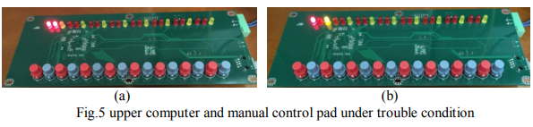
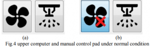
After setting the IP of the upper computer and connecting to the Ethernet with a cable, tests can be started. Firstly click the “connect” button in the upper computer, when “connect to server” appeared in the log, connection is established. Under normal condition, if the start key of the fume extractor in “room one” is pressed, the start, running LEDs will be on and a dynamic graph of the fume extractor will be vividly shown in the upper computer, as is shown in Fig.4(a), Fig.5(a). Click the picture of fume extractor and a “red cross” appears, this indicates the trouble condition. This time when the start key is pressed, the red start LED and yellow trouble LED is on but the fume extractor fails to work, as is shown in Fig .4(b), Fig.5(b). The simulating control of the other equipment is analogous.

Conclusion
The simulation system of the fire-fighting equipment manual-control-pad use TMS320F28335 as CPU. Its high-speed data processing ability ensures the timeliness of sending and receiving data. High-performance Ethernet chip W5300 with integration of TCP protocol decreases the load of CPU, so the performance of the CPU increases significantly. The result of the test indicates that the simulation system achieves the ideal function and works steadily. It is feasible to use it as the simulation training system in power stations.
COMMENTS