Today, I’d share with you how to connect Arduino with PLC S7-300 via Ethernet. From Internet, I also studied some libraries that can handle this communication, such as:
I selected “settimino” library to test communication between Arduino & PLC because of its pro & easy to understand. To get this test, you need to have certain knowledge of PLC Siemens and also have to spend quite money of course….
Cautions:
Do not connect Arduino with Ethernet shield to factory industrial Ethernet network & apply this test. It can cause serious consequences.
With project’s VIDEO below, NODEMCU + MPU6050 is communicated with PLC via WIFI to control Speed/ Direction of DC motor.
Step 1: ARDUINO LIBRARY & PLC SIEMENS
Dave Nardella – Italian – is the author of two great libraries of interfaces between ARM Linux / MIPS microprocessors and PLC Siemens S7 ™:
- Snap7: Snap7 is a cross-platform, open source Ethernet communication library for Siemens PLC (LOGO 0BA7 / 0BA8, S7-200 / 300/400 & CPUs 1200/1500) and Raspberry PI (1 and 2), BeagleBone Black…. Link:
- Settimino: It was rewritten from Snap7 to be compatible with the Arduino platform.
http://settimino.sourceforge.net/
About PLC, you can refer to the Siemens official website:
Step 2: B.O.M
Bill Of Material is as below: 
Important note about Ethernet Shield: The resistor value in the red rectangle should be 49R9 or 510 (about 50 ~ 51 ohm), with some Ethernet Shields, this value is 511 (510 ohm). I have a problem with the 511 resistor so I cannot connect to the PLC & finally have to buy another one with R510, then, the connection is successful. 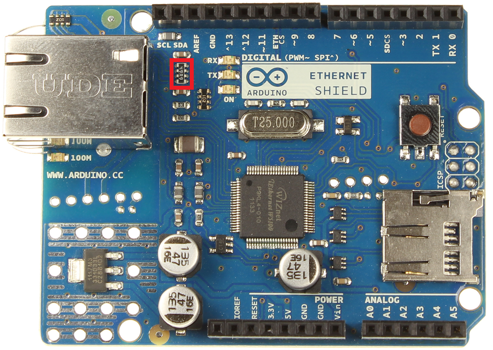
I tested PLC & Arduino communications with 2 options:
- ARDUINO UNO R3 equipped with ARDUINO Ethernet Shield R3.
- NodeMCU ESP 12-E V1.0 standalone & connect via wifi router.
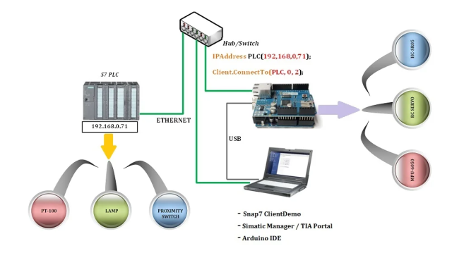
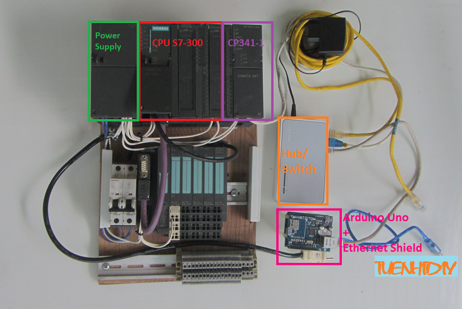
Step 3: HARDWARE CONFIGURATION – ETHERNET SHIELD

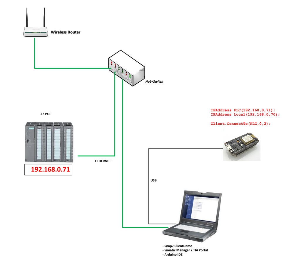
Hardware configuration – ARDUINO UNO R3 equipped with ARDUINO Ethernet Shield R3

Hardware configuration explanation:
- With this configuration you have the freedom to modify both PLC program/Data and Arduino Sketch. And Snap7 ClientDemo is optional.
- In the Arduino IDE, we used ConnectTo () to define the IP_Address, Rack, Slot for the first connection, which set up the internal parameters and connect to the PLC.
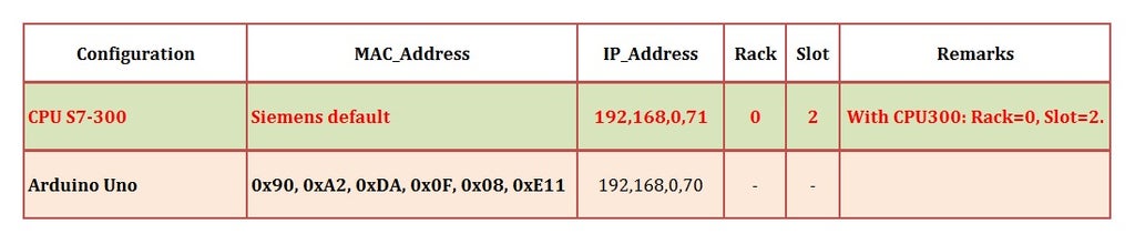
- In the STEP 7 program, the IP_Address of the PLC (CP343-1) must be the address declared in the Arduino program: 192.168.0.71. See details in the image.
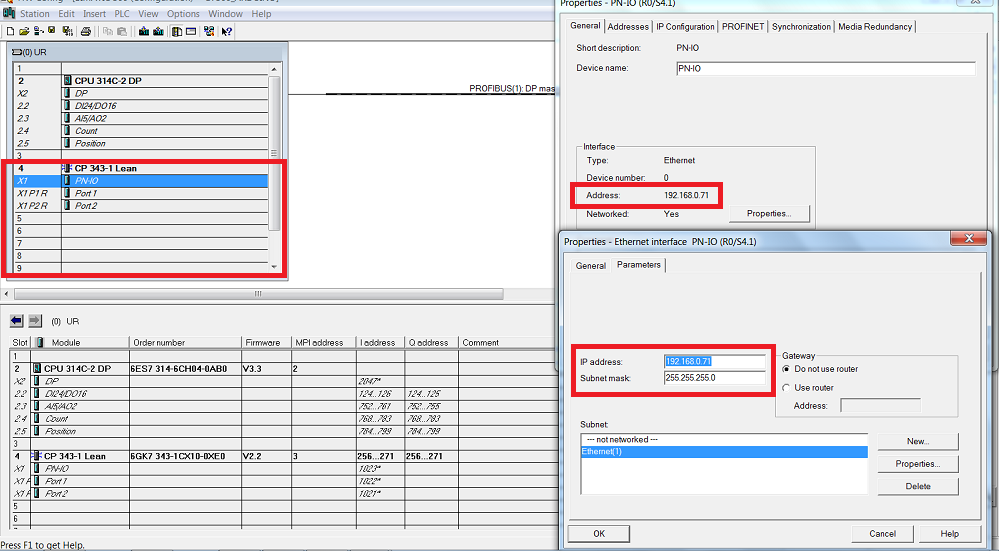
Hardware config in SIMATIC MANAGER
Actual hardware demo kit:

With above configuration, two controllers can exchange data with each other easily, for example:
- PLC side can get the MPU-6050 data, read distance of HC-SR05 or control RC-SERVO.
- Arduino side can read temperature from PT100/ thermocouples, get status of 24V proximity switches, or turn on / off 220VAC lamps.
Step 4: PROGRAM – ETHERNET SHIELD
1. SETTIMINO LIBRARY
You can download the link at: Settimino Library, which includes: library, detailed instructions for using settiminno library and sample programs.
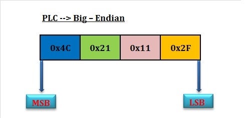
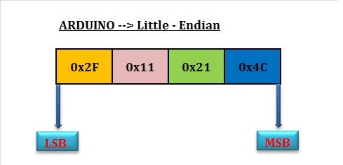
In the manual, please note the terms “Big-Endian” and “Little-Endian” to describe differences in reading and writing data between ARDUINO ™ (Little -Endian) and PLC Siemens S7 ™ ( Big -Endian).
- Big –Endian: MSB (left-most bit) –> LSB (right-most bit), for example, DWORD 0x4C21112F is stored in PLC Siemens S7 ™ as follows:
- Little Endian: LSB (left-most bit) –> MSB (right-most bit), with same DWORD above but ARDUINO ™ will be stored in the opposite way to PLC
2. PLC PROGRAM
I used STEP 7 Professional 2010 V5.5 to configure hardware & write program for PLC. If you are an automatic engineer, you will be very knowledgeable about it…
You can also use the SIMATIC WinCC as an HMI / SCADA system to control Siemens S7 ™ PLCs or ARDUINO ™.
Settimino can directly access the Siemens PLCs with built-in Ethernet moldule (such as CPU 315-2PN/DP, CPU412-2PN/DP, CPU414-3PN/DP …) or via a separated Ethernet card (like CP343 for CPU S7-300), or CP443 for CPU S7-400). I was tested in the case of S7-300 CPU + CP343.
3. ARDUINO PROGRAM
3.1. Arduino read DB values from PLC – “DBGetDemo”
- In PLC program, I created DB2 containing 100 bytes with initial values assigned in order from 0 ~ 99.
- The “DBGetDemo” read 100 bytes values from DB2 and displayed them on the Serial Monitor of Arduino IDE.
- While Arduino reading DB2 from the PLC, I used “FORCE” function to change value of two bytes DB2.DBB0 & DB2.DBB1 to check whether Arduino is reading correctly or not.
Detail you can see at:
3.2. Write to PLC’s Data Block at Security Level 3
Program Overview:
- Enable Security Level 3 (Read / Write Protection) in the CPU300 configuration – Then, Compile & Download to Module.
- In PLC, we created DB1 (Data Block) containing 1,090 bytes with KNOW_HOW_PROTECT (generally speaking, this DB is locked in Siemens terminology).
- The “WriteDemo” program writes the desired value from Arduino to the DB1.DBB0 & DB1.DBB1 being stored in the PLC.
- Change DB1 values by Arduino program and check the PLC’s DB1 online monitoring.
Detail you can check at:
Step 5: HARDWARE CONFIGURATION – NODEMCU ESP 12-E V1.0
Hardware diagram:
Actual system picture:

Wireless router is located inside my home with distance about 15m and it is not shown on the picture.
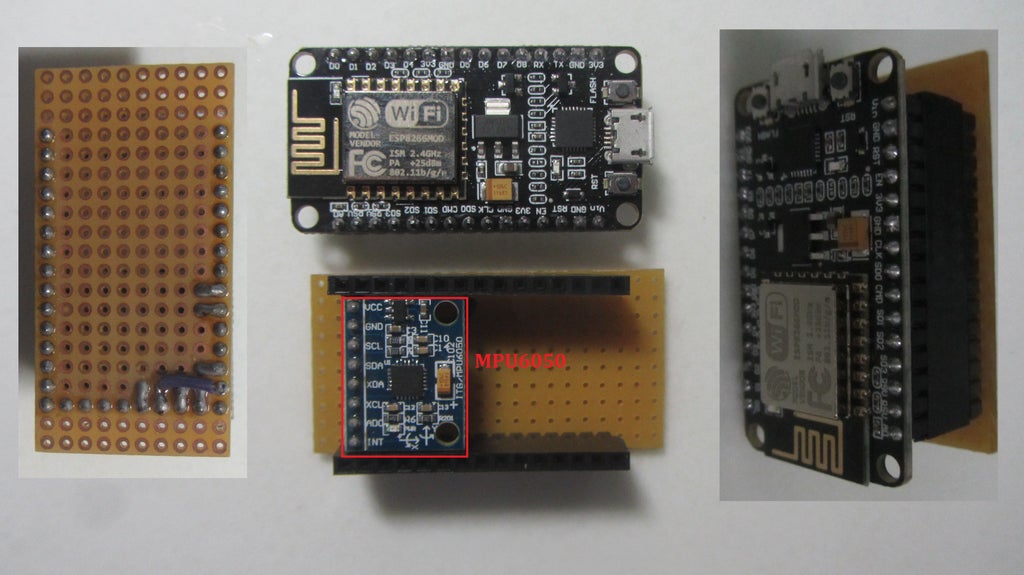
NodeMCU intergate MPU6050 as picture:
Hardware configuration explanation:
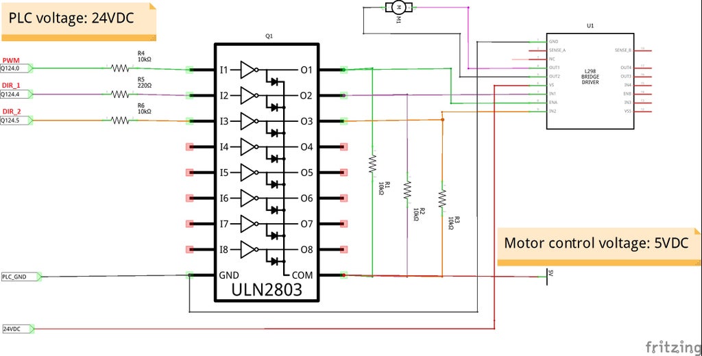
- As picture above, 24VDC PLC outputs are connected to “24V to 5V Converter Board” to change voltage level and then control DC motor through L298N with PWM integrated function inside PLC 314C-2DP. I had to do like that because I didn’t have motor DC drive connecting with PLC.
- NodeMCU + MPU6050 are connected to PLC system by wifi router and it took roll value from MPU6050 to adjust direction & speed of DC motor.
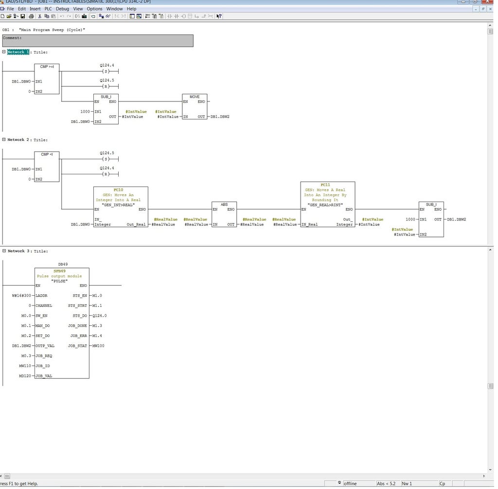
- This demo is based on integrated PWM function in CPU314C-2DP. To control pulse width modulation via the user program, we use SFB 49 “PULSE”. The following operations are available:
- * Starting/stopping via software gate SW_EN.
- * Enabling/controlling the output DO.
- * Retrieving the status bits STS_EN, STS_STRT and STS_DO.
- * Input of the output value.
- * Jobs for reading/writing the registers.
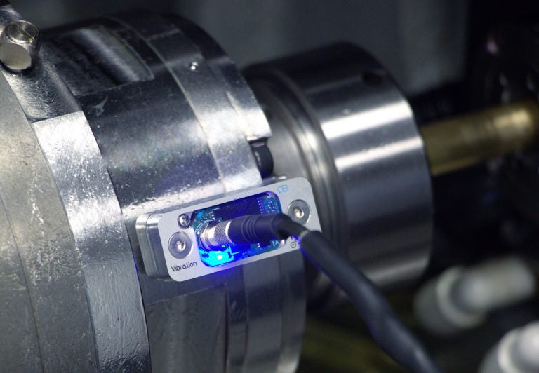
- From beginning of this project, my purpose is making a vibration sensor that can be integrated to industrial network, something like: https://www.dytran.com/Series-7556A-Analog-6D-Sen…It will be very cheap & useful for vibration protect or vibration analysis. For example with high power motor, it can be attached on gearbox and take 6DOF vibration data for analysis or popup alarm to PLC system when vibration is higher than limit. Or we can use it as portable analysis device for prevented maintenance. With this demo, it’s just start point & it can be come true with acceptable sampling time.

Step 6: ARDUINO PROGRAM – NODEMCU ESP 12-E V1.0
Step 7: PLC PROGRAM – NODEMCU ESP 12-E V1.0
PLC program control DC motor:
- Motor direction (CW or CCW) is according to MPU6050 – ROLL VALUE (Positive or Negative). Q124.4.& Q124.5 connected to “Converter board” and L298N at pin IN1, IN2 to set motor direction.
- And motor speed – DB1.DBW2 – is ABS(ROLL VALUE). PLC PWM output Q124.0 is connected to “Coverter board” & L298N at pin ENA to control PWM of DC motor.
- SFB49 was used in ladder program below to generate PWM at output channel 0 – Q124.0.
Step 8: 24V TO 5V CONVERTER BOARD
I used ULN2803 to convert the voltage level. Each ULN2803 contain eight darling-ton transistors, it means we can convert 8 signals by using one ULN2803. Circuit diagram as follow:
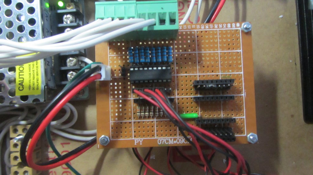
Picture of Converter Board
Step 9: MORE PICTURES & VIDEOS


About this project, you can check at my channel address:
And more videos for PLC project at:
Step 10: SUMMARY
- With S7-300 PLC in this test, Settimino can almost read / write to the PLC regardless of the CPU Protection Level. This security issue caused certainly a great deal of difficulty for automation engineers who work with Siemens ™ CPUs.
- Arduino is not compatible with industrial environments such as dust, humidity, temperature, and cannot meet reliability requirements as PLC. But more or less, this is not bad way for us to make IoT / Smart Home using new generation CPUs Siemens with built-in Ethernet port, affordable, in conjunction with the Arduino.
- Special thank to Dave Nardella for “settimino” library….
PLEASE VOTE FOR ME … so that I have more motivation to do more useful projects!!!
COMMENTS