The aim of this project is to provide an FPGA implementation of the Phasor Estimation algorithm in this paper: https://ieeexplore.ieee.org/document/6547769
This algorithm should be very suitable for FPGA implementation, due to it consisting of mostly MAC instructions followed by a single arctan.
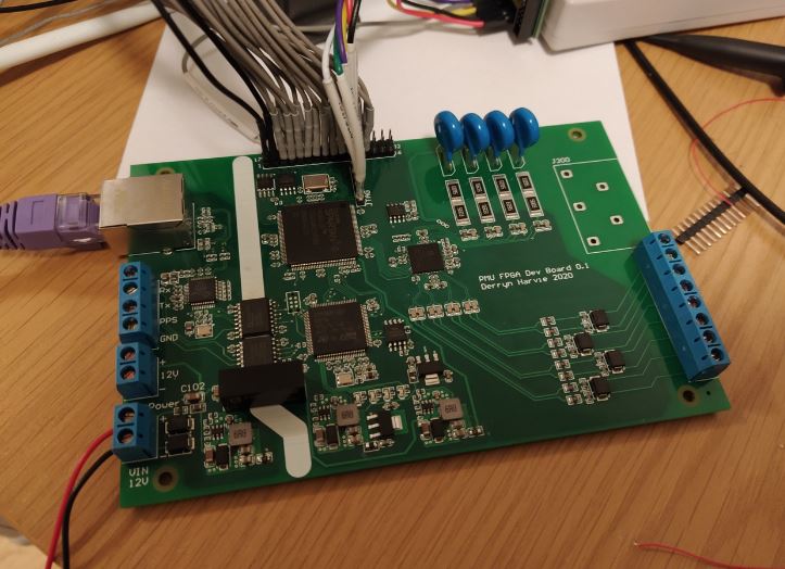
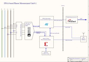
The design currently has a Q-SPI flash memory to store the coefficient library for the LES algorithm, with the rest of the main algorithm to be implemented in the Xilinx S6 FPGA.
The STM32 is to act as a communications controller, and provide supervision for the system. The STM32 also has an external SPI flash memory which will hold the ROM image for the FPGA, and double as an in-system software update buffer (i.e. upload new firmware over Ethernet to the flash, then reprogram off the flash.)
A Q-SPI PSRAM memory is also added to the FPGA to form a circular buffer for samples. When some trigger condition is met, this will form the center point of the sample collection window, with the intent that the samples will be uploaded to a server for post analysis. i.e. effectively a fault recorder.
COMMENTS