
Inter net of Things (IOT) is extension of networking access through web asses connection, and sment communication, Internetworking between varied devices or physical objects additionally framed as “Things.” During this proposed work the system tend to additionall any devices y give fault detection and correction in Connected to the present system mechanically. Now a days as a result of large advancement in wireless device network and different computation technologies, it’s attainable to supply flexible and low value home automation system. It can be used for person status and which location by using GPS. During this system we tend to use prediction to search out the desired answer if any downside occurs in any device connected to the system. Internet of Things ( in this project. IOT) technology is used Keywords: IOT, GPS, Physical Objects, Fault Detection and Correction. Introduction: This paper proposed to design a system that works using GPS and IOT technology. This system built based on embedded system, used fo r person status and locations by using Global Positioning System (GPS) and Internet of Things (IOT). All the data transferred to the IOT devices. This proposed technology is used for report the person’s status and locations of the place. Specification of E thernet Shield
The most recent revision of the board exposes the 1.0 pin out on rev 3 of the Arduino UNO board. The Ethernet Shield has a standard RJ45 connection, with an integrated line transformer and Power over Ethernet enabled. There is an onboard microSD card s lot, which can be used to store files for serving over the network. It incompatible with the Arduino Uno and Mega (using the Ethernet library). The onboard microSD card reader is accessible through the SD Library. When working with this library, SS is on P in 4. The original revision of the shield contained a full size SD card slot; this is not supported.(811)The shield also includes a reset controller, to ensure that the W5100 Ethernet module is properly reset on power up. Previous revisions of the shiel d were not compatible with the Mega and need to be manually reset after powerup. The current shield has a Power over Ethernet (POE) module designed to extract power from a conventional Twisted Pair Category 5 Ethernet Cable: IEEE802.3af compliant Low ou tput ripple and noise (100mVpp) Input voltage range 36V to 57V Overload and shortcircuit protection 9V Output High efficiency DC/DC converter: typ 75% @ 50% load 1500V isolation (input to output ) NB: the Power over Ethernet module is proprietary har dware not made by Arduino; it is a third party accessory. For more information, see the datasheet The shield does not come with the POE module built in; it is a separate component that must be added on. Arduino communicates with both the W5100 and SD card using the SPI bus (through the ICSP header). This is on digital pins 11, 12, and 13 on the Duemilanove and pins 50, 51, and 52 on the Mega. On both boards, pin 10 is used to select the W5100 and pin 4 for the SD card. These pins cannot be used for general I/O. On the Mega, the hardware SS pin, 53, is not used to select either the W5100 or the SD card, but it must be kept as an output or the SPI interface won’t work (1719) Note that because the W5100 and SD card share the SPI bus, only one can be active at a time. If you are using both peripherals in your program, this should be taken care of by the corresponding libraries. If you’re not using one of the peripherals in your program, however, you’ll need to explicitly deselect it. To do this with the SD card, set pin 4 as an output
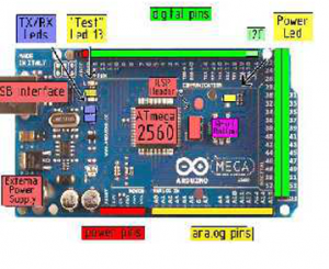
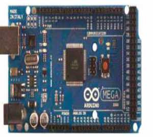
The Arduino Mega 2560 is a microcontroller board based on the ATmega2560 (datasheet). It has 54 digital input/output pins (of which 14 can be used as PWM outputs),16 analog inputs, 4 UARTs (hardware serial ports), a 16 MHz crystal oscillator, a USB Connection, a power jack, an ICSP header, and a reset button. It contains everything needed to support themicrocontroller; simply connect it to a computer with a USB cable or power it with a AC-toDC adapter or battery to get started. The Mega is compatible with most shields designed for the Arduino Duemilan over or Diecimila
and write a high to it. For the W5100, set digital pin 10 as a high output. The shield provides a standard RJ45 Ethernet jack. The reset button on the shield resets both the W5100 and the Arduino board. (12 The shield contains16) a number of informational LEDs: PWR: indicates that the board and shield are powered LINK : indicates the presence of a network link and flashes when the shield transmits or receives data FULLD: indicates that the network connection is full duplex 100 M: indicates the presence of a 100 Mb/s network connection (as opposed to 10 Mb/s) RX: flashes when the shield receives data TX: flashes when the shield sends data COLL: flashes when network collisions are detected The solder jumper marked “INT” can be connected to allow the Arduino board to receive interruptdriven notification of events from the W5100, but this is not supported by the Ethernet library. The jumper connects the INT pin of the W5100 to digital pin 2 of the Arduino. Ethernet library refer ence By means of judiciously roundingoff the elements of the exact DCT matrix, a DCT approximation was obtained and described in [11]. The resulting 8point approximation matrix is orthogonal and contains only elements in {0, ± 1} Clearly, It possesses v ery low . arithmetic complexity 11
COMMENTS