Many of the projects presented on this blog use an nrf24l01+ module for wireless data transmission… that’s good, you still need something at the other end to receive them. The goal of today’s post is to build a two-way gateway between an Ethernet network and nrf24l01+ modules. The packet transmitted by a sensor can thus be sent to an API hosted on a NAS or on an internet server via a box connected to the network. Conversely, a web page can call the gateway API to send a packet to a sensor.

List of materials used
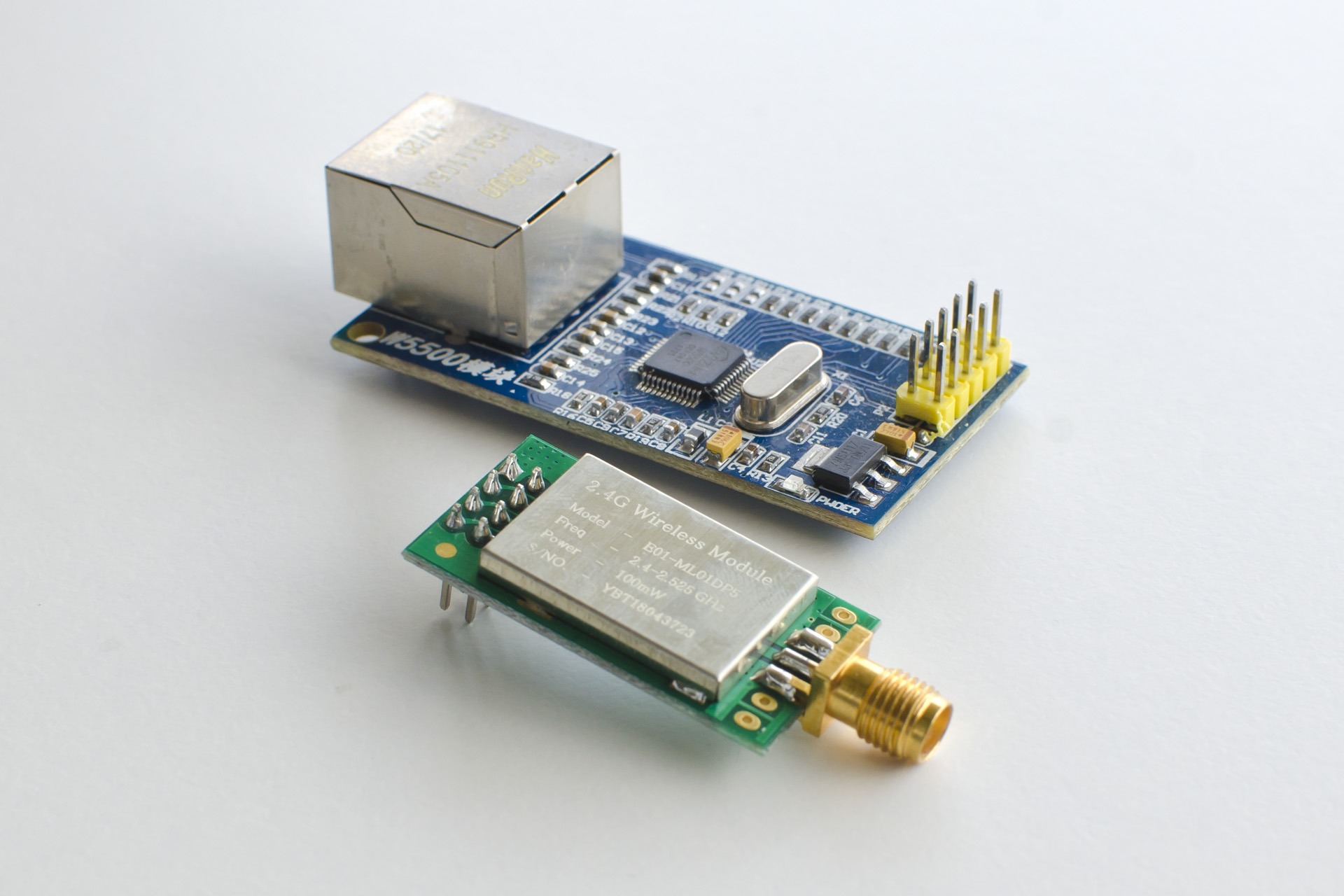
- An amplified Nrf24l01+ module with SMA connector for the antenna (model E01 ML01DP5)
- A W5500 module
- A 128X64 I2C SSD1306 0.96″ OLED display
- An aluminum box 100x75x36mm
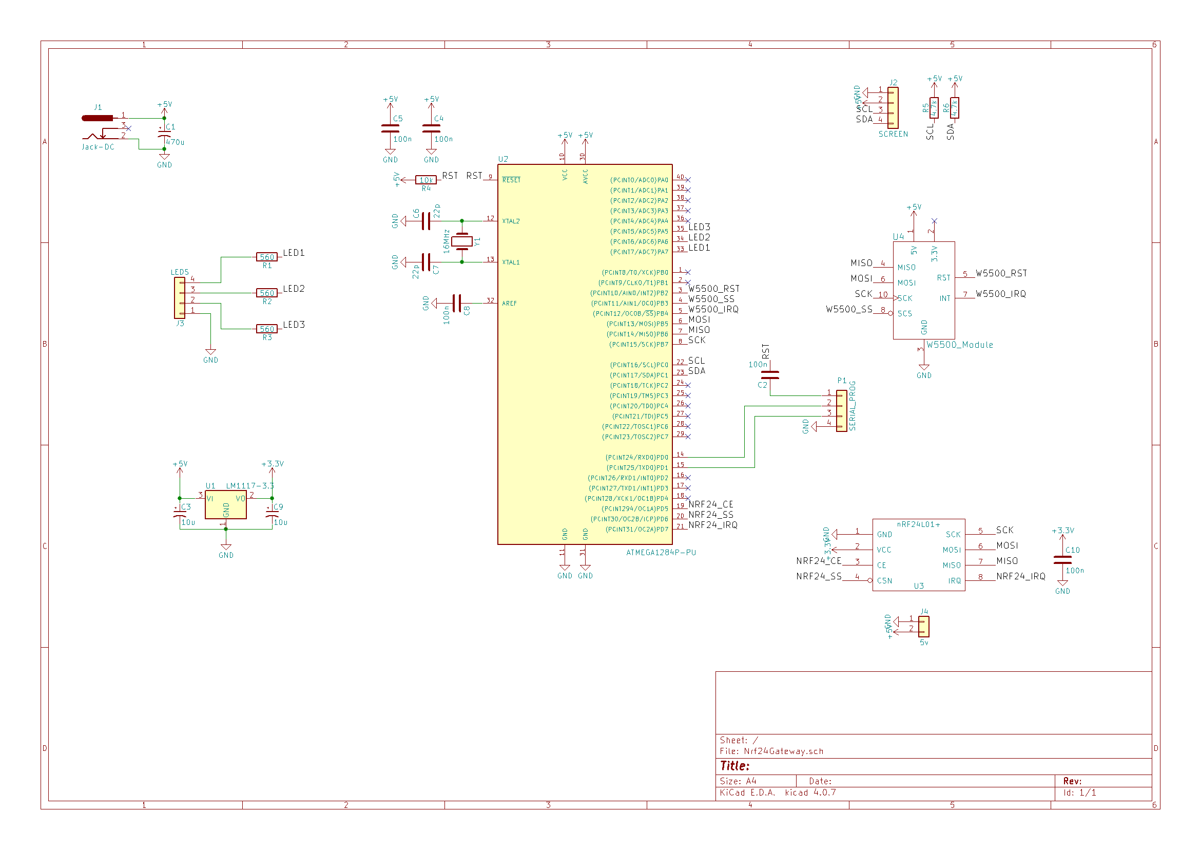
Circuit diagram
The microcontroller this time is an ATMega1284P which has more RAM than the ATMega328P often used on other posts. There are few other components, the W5500 module and the NRF24 module are both connected to the SPI bus, the screen on the I2C. Three outputs for LEDs were planned but ultimately they are not used. A regulator provides the 3.3V necessary for the NRF24 from the 5V of the power supply. Although powered at 3.3V, the NRF24 and the W5500 have 5V compatible I/Os.
| U4 | W5500 module (with 2×5 female support) |
| D4 | 1×2 female pin header (optional, provided for an adapter for another wireless module such as Lora, RFM69, etc.) |
| U3 | nRF24L01+ module (with 2×4 female support) |
| D1 | Jack DC |
| U2 | ATMEGA1284P-PU + Bracket |
| C1 | 470µF |
| C4,C5,C8,C2,C10 | 100nF (SMD 0805) |
| C6,C7 | 22pF (SMD 0805) |
| J2 | Pin header 1×4 (screen) |
| R1,R2,R3 | 560Ω |
| R4 | 10kΩ |
| R5,R6 | 4.7kΩ |
| Y1 | 16MHz |
| D3 | 1×4 pin header (unused LEDs) |
| P1 | Pin header 1×4 (serial port programming) |
| C3,C9 | 10uF |
| U1 | LM1117-3.3 or AMS1117-3.3 or equivalent |
Artwork files for the printed circuit with the solder mask, be careful it’s a double sided!
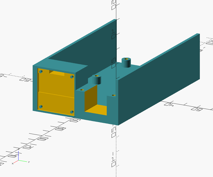
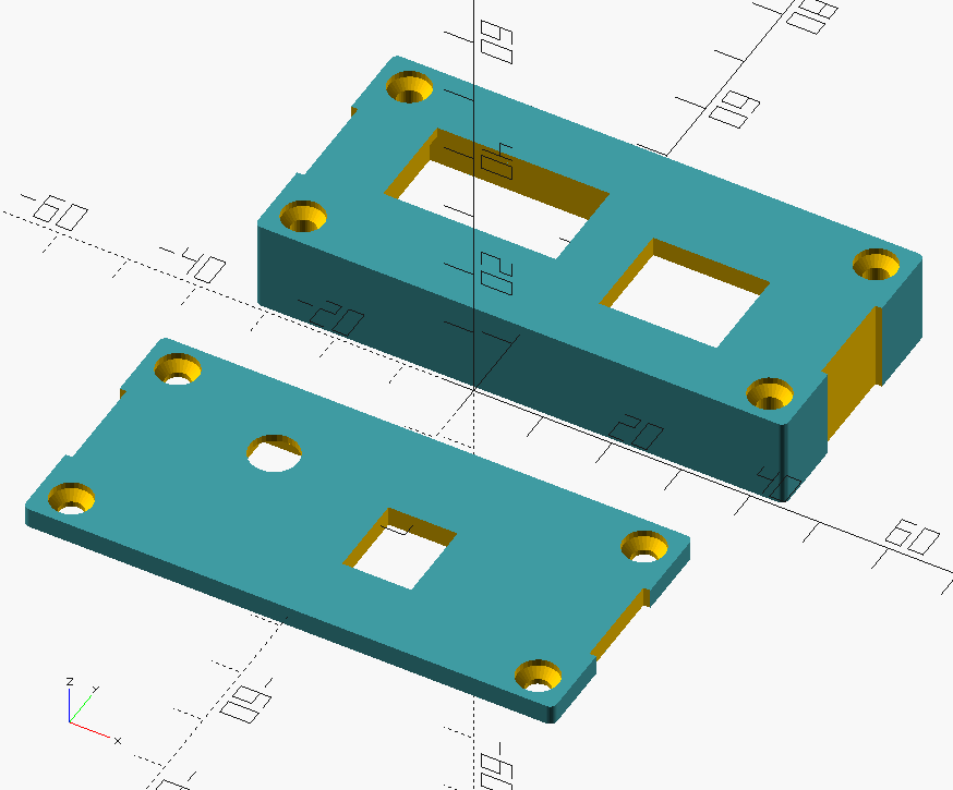
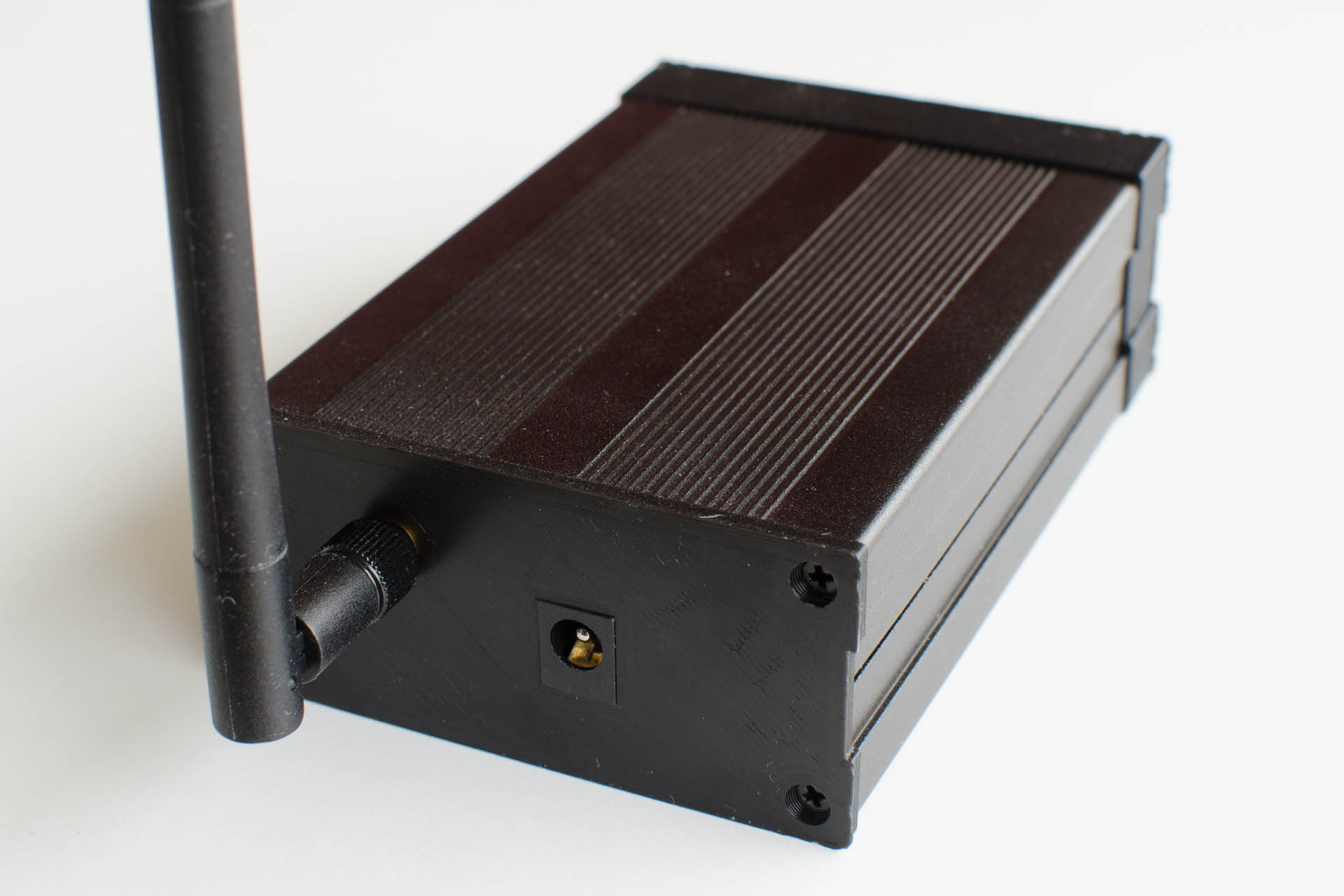
The box
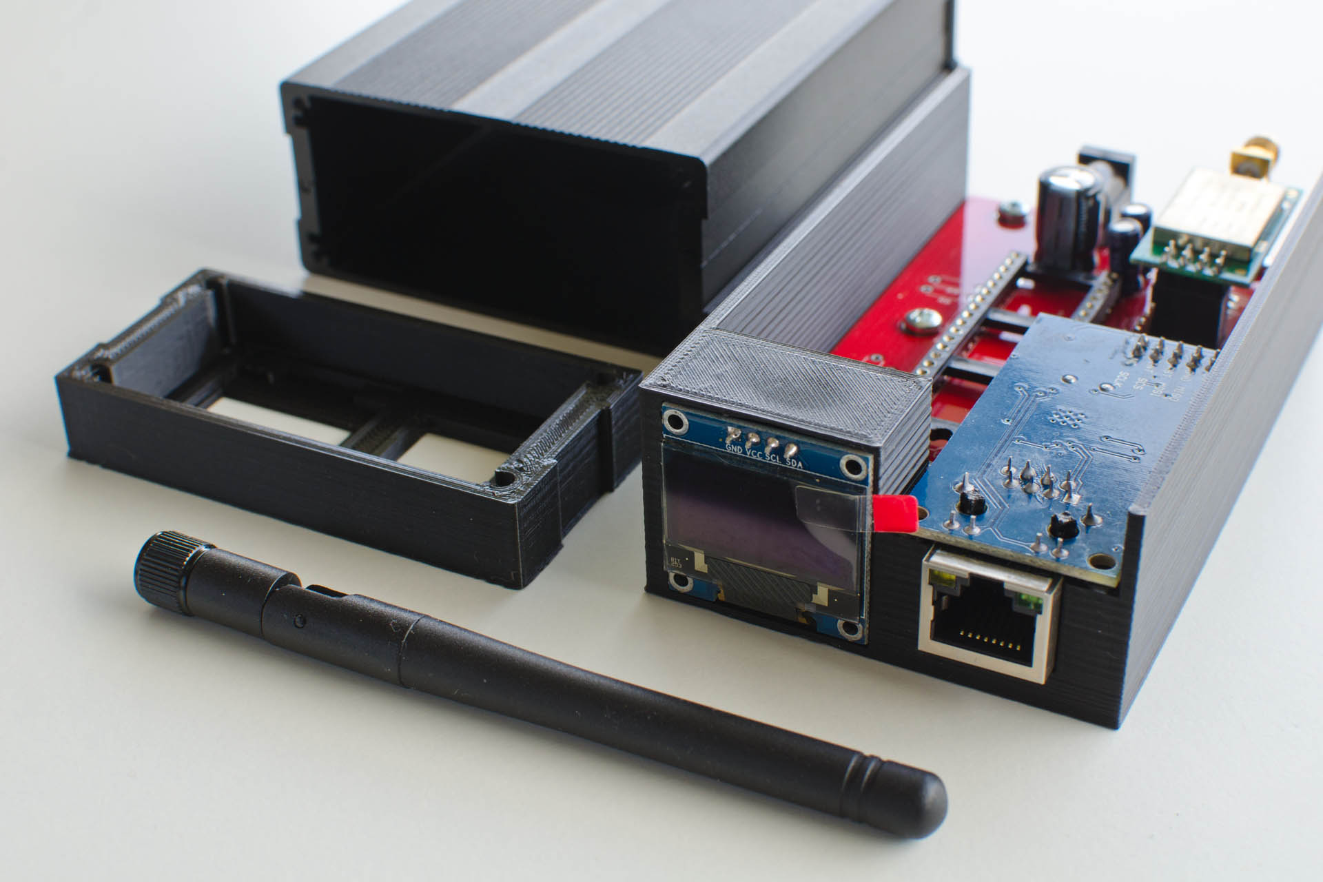
The case is composed of an aluminum body (Enclosure Electronic Project Case 100x76x35mm), a front face and a back face made with a 3D printer in black PLA. Inside, a support also printed holds the printed circuit, the RJ45 socket and the screen. It is made with OpenScad.
Enclosure sources: Nrf24Gateway_Enclosure.zip
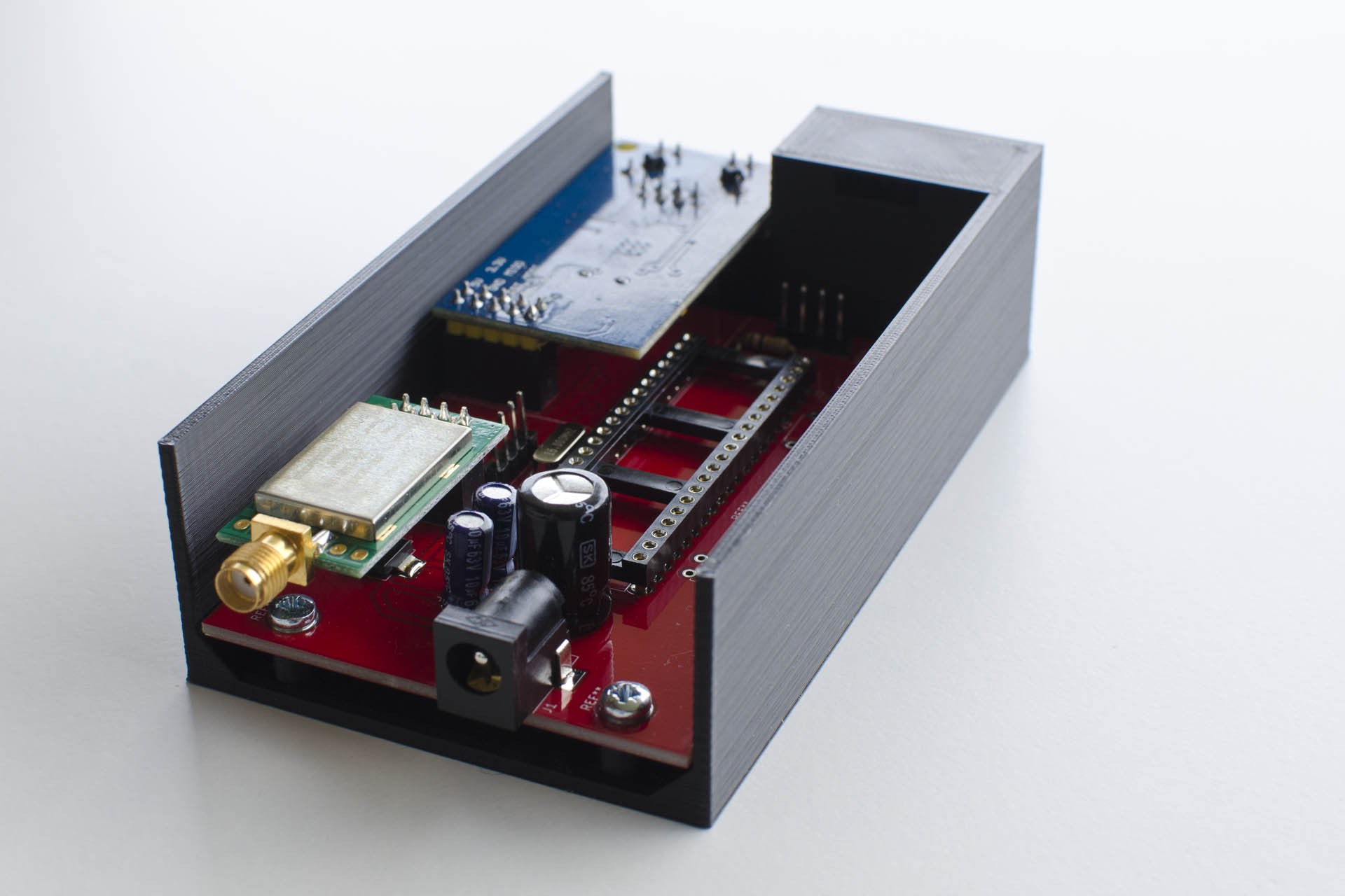
Assembly
The program
To program the ATmega1284P, you must first install the MightyCore library ( https://github.com/MCUdude/MightyCore ) by following the instructions, which allows you to add this microcontroller as an Arduino board in the editor.
Download Firmware: Nrf24Gateway
Libraries used:

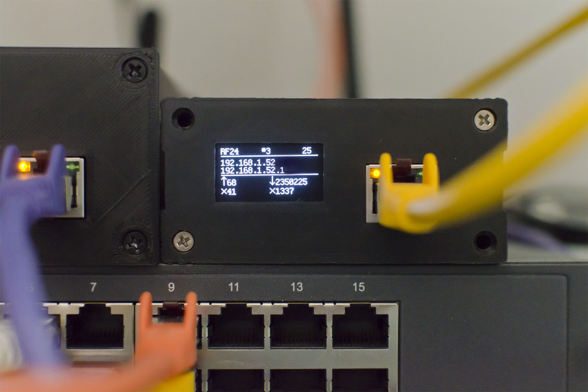
Functioning
On the screen on the front there is:
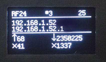
- The radio module used (here RF24, but the gateway can be adapted for another radio module

- The gateway id
- The radio channel used
- IP address
- The NRF24 address
- The number of packets transmitted/received successfully and in error.

Send data
Via une requête GET (oui c’est mal niveau REST) : http://192.168.1.100/send?recipient=0120212325&data=0100000000FF55D00700000112FF00D007000001000000000000000000000000 ou recipient est l’adresse du nrf24 destinataire en hexadécimal, et data le paquet de 32 octets en hexadécimal also.
Receive data
The gateway automatically receives radio messages and sends them via a POST request in json to the server address configured in the firmware:
COMMENTS