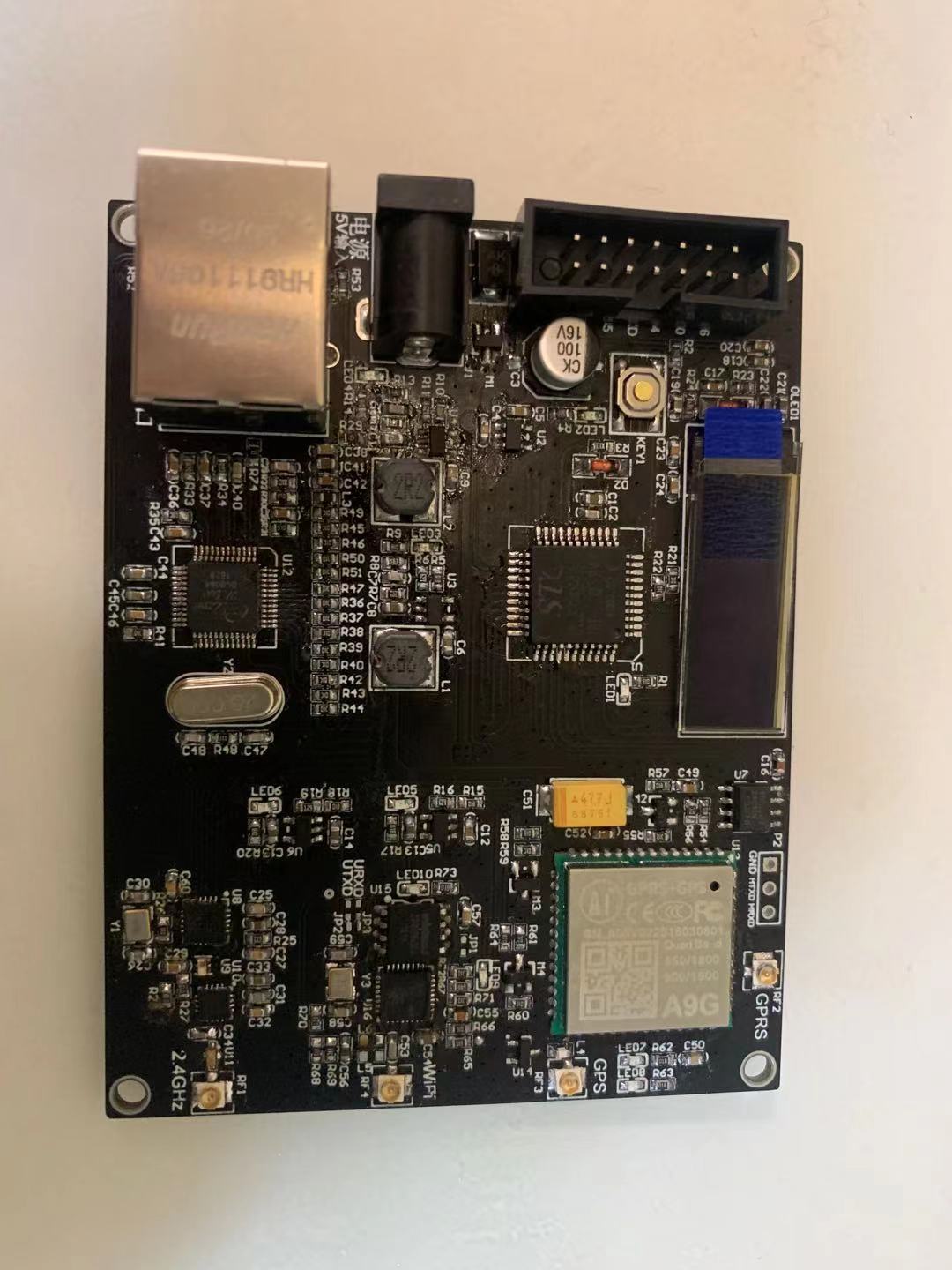
Name: Multifunctional IoT Concentrator V2
Multifunctional IOT concentratorV2
note1: Make by MikeXUE
note2: 20210102
note3: The module design is the bottom chip design, no integrated module
note4: centralized communication module with multiple wireless communication methods
note5: The actual project of this design module is used as a communication sub-module of the project
note6: “|hardware open source|”
Module size: 70mmX90mm
1. Function overview
◆ 5VDC power input, it is recommended that the maximum current of the power supply can reach 2A
◆ A variety of wireless communication methods, you can choose the appropriate communication method according to the actual situation
◆ With wired Ethernet communication function
◆ With GPRS or GSM communication function
◆ With WiFi communication function
◆ With 2.4GHz wireless communication function
◆ With GPS and Beidou positioning function
◆ A 0.91-inch OLED display for displaying communication information
◆ Has a plug-in eeprom memory for saving work information
◆ A 14P interface, including a set of 5V power input interfaces and reserved 10 GPIOs (including a set of UART ports)
◆ Each communication unit has a controllable independent power supply unit
◆ The antennas of each wireless communication unit use IPEX terminals to connect the antennas
◆ Both the A9G unit and the WiFi unit have reserved firmware and new ports (refer to the schematic diagram for details)
◆ One extended micro switch
Second, the circuit overview
1. The power supply circuit includes 5 units, which are GPRS/GPS circuit, Ethernet circuit, WiFi circuit, 2.4GHz circuit, and MCU onboard circuit to supply power.
According to the energy consumption requirements of different circuits, SY8089\ME6119 chips are used to form the corresponding voltage regulator circuits.
Except for the on-board regulated power supply circuit of the MCU, the other 4 voltage stabilizing circuits are all controllable, all of which are low-level disabled regulated outputs and high-level enabled outputs.
2. MCU adopts 51 single-chip microcomputer, model STC8A8K64S4A12 core, LQPF44 package;
3. OLED adopts 0.91-inch I2C bare screen;
4. eeprom adopts AT24CxxAN chip, I2C communication bus is shared with OLED.
5. The 2.4GHz wireless communication unit is composed of nRF24L01-REEL+2450BM14A0002+RFX2401C+2450BP14D0100;
6. The Ethernet communication unit is composed of W5500+HR911105A;
7. The GPRS/GMS&GPS&DB unit is composed of A9G module and external level conversion circuit, and the key control signal refers to the description in the schematic diagram;
8. WiFi unit, composed of ESP8266EX+25Q32;
9. The power input circuit is composed of TVS+PMOS, with transient suppression function and anti-reverse connection protection;
3. Instructions for use
1. The J1 port is a 5V input port (you only need to connect any one of the 5V power input ports of J1 and P1);
2. P1 is a reserved port for the module, including a 5V input port, 10 GPIOs, and a set of UART interfaces, which can be used to communicate with other circuits;
3. The J2 port is an Ethernet port for connecting a network cable;
4. CARD1 is a flow card socket, used for GPRS or GSM communication, it can be plugged in if not used, it will not affect the use of GPS&BD;
5. RF1 is 2.4GHz antenna interface;
6. RF2 is GPRS/GSM antenna interface;
7. RF3 is the GPS/BD antenna interface;
8. RF4 is the WiFi antenna interface;
9. The related chips in the circuit are easy to find on the Internet, and the attachments are no longer uploaded;
4. Application Examples
This design module is used as a sub-module in the actual project to automatically identify the communication method of accessing the server (because of the wide range of on-site use, it may have WIFI coverage or only Ethernet or only GPRS/GSM),
Connect to the specified server in any of the above ways;
2.4GHz wireless communication is used to communicate with other 2.4GHz wireless nodes, collect data, and then send the data to the server and send the control commands sent by the server to other 2.4GHz nodes through one of the above methods;
The P1 port only uses the UART communication port, which is connected to another main board to exchange data with the main board, configure server IP or configure WIFI and other information through serial communication, and control information or server information;
OLED is used to display the status of network connection, 2.4GHz communication status, etc.
The micro switch is used to wake up the OLED screen, and the OLED screen will automatically turn off after working for 1 minute to enter low power consumption
5. Remarks
The module can be used for learning friends to learn the design of related hardware circuits, and can also be used to learn software development
The module can be used as a standalone wireless concentrator
The module can also be used as a communication unit with an independently developed control board.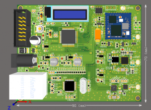
COMMENTS