
1. INTRODUCTION
PLC is used for transmitting (50/60 Hz 220/110 V) power signal. It is not designed to convey high frequency signal such as 20 MHz communication signals used in the home plug 1 protocol. A power line channel is somewhat wireless channel, both suffer from noise, fading, multipath, and interference. Power line noise is produced by operation of electrical device. Fading, multipath and interference are caused by the imperfection of power line channels. Also limits the available bandwidth for communication purposes. In compliance the usable bandwidth in the home plug standard is 25MHz. There an extensive on going studies of power line channel characteristic. To conquer the above problems, robust signal modulation and data coding are needed.
2. THE PROBLEM
Traditionally, device control is usually achieved through direct physical contact (wire) between computer and the device to be controlled. In huge control system that extends for long distance; the wires have available resource. Thus, the idea of replacing the wires with one of the available resources to reduce the total cost takes place. One of these resources is alternative current (AC) power lines that are used in all of the power systems to transfer electricity to consumption area. Those wires are available in the electric systems, so, I can use them as a transmission medium to transmit control signals that to transmitted to different part of the system, so that I get rid of an extra cost that arise from purchasing wires
3. OBJECTIVE OF THE STUDY
The main aim of this paper is to design and develop a remote control system in the real time using the power lines such that it can communicate with maximum efficiency. This device is:
1. Economical
2. User friendly
3. Reliable
Design remote control system replacing the conventional wires with AC power lines to reduce the total cost.
Design special receiver to detect the high frequency control signals.
4. METHODOLOGY OF THE SYSTEM
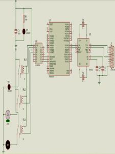
This system contains two components which are the hardware and software components. On the hardware part, the power line transmission function needed to be developed with the ATMEGA microcontroller in order to control appliances through power line. Interfacing of power line modem with ATMEGA microcontroller is the main part of the hardware while the software part requires designing a control system panel that is able to interact with the hardware. Microsoft Visual basic 2010 software has been chosen in this paper to design the control interface and serial communication is used to connect the system with the control interface. All the operation of the system with control interface is using the serial port communication.
5. HARDWARE ORIENTATION OF REMOTE CONTROL SYSTEM
With the proposed system to be designed certain hardware components are required. These are as follows
1. Two PLM.
2. WIZ 110SR.
3. Personal Computer.
4. MAX 232
5. ATMEGA 16L microcontroller.
6. Serial communication cable.
7.ULN2003
8. Three relays
9. Two RJ-45 cable
10. Electric deviceS (fan ,motor ,LED)
11. Five capacitors (1×1000 μF + 4×1μF).
12. Resistant (100 Ω)
13. 5V DC adaptor.
6. METHODS AND MATERIALS
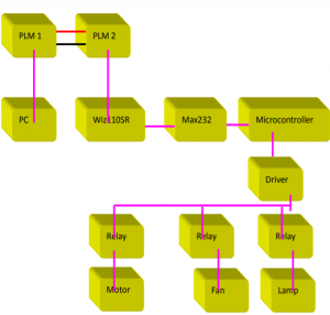
The hardware development of the GUI Based Remote On/Off Control and Monitoring Single Phase Automation Device is as shown in Figure 1. The system consists of a personal computer (PC) as a main controller with the ATMEGA 16L microcontroller circuit system which acts as a slave unit. The proposed technique of centralization
utilizes a concept of master/slave communication. In this system, one master device controls the other slave units. All these slave units have their own unique identification address. When the slave units receive the same address data, they extract the address from the master and compare it with their identification address. The slave units with matching addresses will send back the address to the master devices for confirmation for a successful transfer. This is aided by an auto handshaking line driver for transmitting and receiving which is controlled by the ATMEGA 16L microcontroller. The slave units are controlled using the ATMEGA 16L microcontrollers, which provide serialembedded communication to external link configurations through the software.
7. FUNCTIONAL DESCRIPTION:
In this system the data is being transferred over AC line from PC communication port, which is encoded and decoded by PLC chips. The circuit contains PC on one side and microcontroller based relay switching drives on another side. I send the data using program prepared in Visual Basic (VB) through Ethernet port. This Ethernet port is connected to PLM. This PLM is assigned supply of 230V mains. On the receiver side, same circuit is connected to power line on the same phase. This circuit receives data from the PC attached with the circuit which is connected to ATMEGA 16L microcontroller
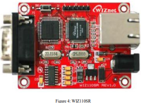
7.2 WIZ119SR
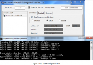
WIZ110SR is a gateway module that converts RS-232 protocol into TCP/IP protocol. It enables remote gauging, managing and control of a device through the network based on Ethernet and TCP/IP by connecting to the existing equipment with RS-232 serial interface. WIZ110SR (figure.4) is a protocol converter that transmits the data sent by serial equipment as TCP/IP data type and converts back the TCP/IP data received through the network into serial data to transmit back to the equipment. When the data is received from serial port, it is sent to W5100 by MCU. If any data is transmitted from Ethernet, it is received in the internal buffer if W5100, and sent to the serial port by MCU. MCU in the module controls the data according to the configuration value that user defined (figure.5); we configure wiznet to take THCP IP and to work as client and server.
8. TEST SET UP FOR REMOTE CONTROL
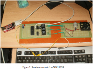
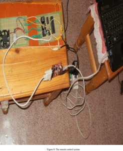
The Test setup for remote control over power line is as shown in figures 6 ,7 and 8. The figure 6 indicates the receiver and figure 7 indicates the receiver connected to WIZ110SR. Figure 8 indicates the transceiver connected to the electrical sink at two different ends inside a building for data transmission and device control.
9. CONCLUSION
Power line communication provides an alternative way of communication. This paper provides an efficient way of control through the existing power lines as a communication medium. my system is more applicable in large industries, schools or in hospitals where we want to communicate between various departments.
10. ADVANTAGES
The advantages of the system are as listed below:
No need for additional networking: The power grid is ubiquitous; it constitutes an existing network infrastructure to billions of private consumers and businesses. The power grid offers last-mile conductivity. The power grid supports information based services with strong growth potential.
High transmission rate: Right now 40 Mbps in uploading and downloading. The data transmission rate is expected up to 200 Mbps in the future by improving the PLC chip. this technology may be used to provide broad band internet over ordinary power lines.
Lower investment cost: Lower costs are achieved because the service is implemented on standard electrical lines. The service is also convenient because it’s already in your home.
Security service: Greater security (all products are sold with encryption turned on)
Simplicity: Setup takes just a few minutes – just plug in!
Safety :This system can be used in Nuclear Power Stations or Power Grid Stations, which are very hazardous for human beings to work in and needs heavy data transmission between the points.
COMMENTS