The HomeBridge configuration file
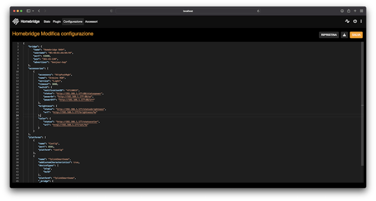
The core of the HomeBridge configuration and customization is a JSON file. HomeBridge makes easy to access and modify it by loading it in a in-browser editor that can easily be accessed in the “Configuration” panel.
Here you have to make you first important decision, the IP address you want to set for your Arduino. You can always change it later, if you want. The configuration you most likely want to use for this accessory is the following.
Paste it inside the “accessories” brackets
{
     "accessory": "HttpPushRgb",
     "name": "Arduino RGB",
     "service": "Light",
     "timeout": 3000,
     "switch": {
         "notificationID": "47110815",
         "status": "http://192.168.1.177/statuspower",
         "powerOn": "http://192.168.1.177/on",
         "powerOff": "http://192.168.1.177/off"
      },
     "brightness": {
         "status": "http://192.168.1.177/statusbrightness",
         "url": "http://192.168.1.177/brightness/%s"
     },
     "color": {
         "status": "http://192.168.1.177/statuscolor",
         "url": "http://192.168.1.177/set/%s"
     }
 }
To set the accessory name, edit the “name” field. If you want to keep the IP address I used, there’s no problem. At the end, you should see a screen like this one.
To apply these changes, you have to save the file by clicking the orange save button, then restart HomeBridge by clicking the shut-down icon in the top-right (it will start pulsing after having saved the file)
By opening the Home app, you now should see the accessory being automatically added.
Arduino, finally
Yes, finally we are back on it. Also for the LED setup I used what I already had, this is what I used:
- a cheap and generic 12V LED strip
- some MOSFETS
- some 1k ohm resistors
- a 12V power adapter (previously used to power a broken router)
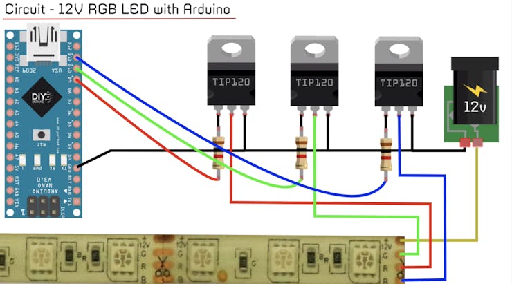
I followed this simple but complete tutorial, this is the scheme for the wiring
If you want, you can attach a simple push-button and use it as a “manual switch”, this will also change the status on HomeKit by sending a notification to the server. Attaching a button shouldn’t be that hard, but there’s a good tutorial on how to do it 🙂
Speaking of code, it’s not that complex. If you can’t wait to test this out, you can directly upload it to your board without spending time watching at it. But stop! First you should check the defined pinout for the RGB channels and the button, then set the correct HomeBridge server IP address and the address chosen for your board.
// connections of the three LED outputs and the button input
#define outRed 3
#define outGreen 5
#define outBlue 6
#define switchButton 7
// network properties
char homebridgeServer[] = "xxx.xxx.xxx.xxx"; // your HomeBridge server IP address
int homebridgePort = 8581;
IPAddress ip(192, 168, 1, 177); // IP address of Arduino (must be equal to the one set on homebridge!)
The main address you want to focus on changing is the HomeBridge server address, this can be immediate to set if the machine where you host HomeBridge has a static IP address (a Pi, for example). In my case, my computer hasn’t a static IP address inside the LAN, and I didn’t want to set a static address just for this project. If you hare in the same situation as mine, you can use the .local mDNS address that most of the routers provide to every single host (in my case, the address I set was “myMacExample.local”, the mDNS server of your router will automatically resolve this address and prompt the request to the right IP address).
You can always check your HomeBridge server address in the HomeBridge dashboard, right under the QR code image. If you plan to use HomeBridge on a daily basis, I really suggest you to assign a static IP address to the machine hosting it.
Last but not least, check that the Arduino’s IP address set in the sketch is equal to the one set in the HomeBridge configuration file.
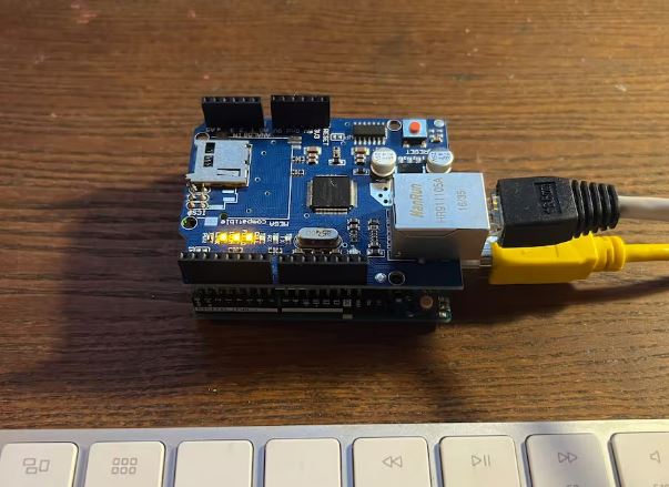
Having done all of that, you can now stick the Ethernet Shield onto Arduino, plug in the Ethernet cable and load the sketch.
COMMENTS