
1. Introduction
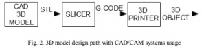
The idea of the spatial (three-dimensional) printing, understood as the process of creating real objects of arbitrary shape based on a computer model is not new. The technology was developed already in 1980 leading to the establishment of the first operating structure in 1984 by 3D Systems company [1]. There are several methods of 3D printing. The more popular include: FDM – Fused Deposition Modeling and DMLS – Direct Metal Laser Sintering. Suitable examples of the FDM and DMLS printing are presented in Figure 1. The first method (FDM) based on the extraction of plasticized material by following the head by path coordinated with extrusion process. A layer-by layer, reference model geometry of the spatial object is created.
With the opening of the technology (caused by international patents expiring), the idea of universal, self-replicating machines is born. The expression of that idea is three-dimensional printer. Around this idea, the RepRap (shortcut for Replicating Rapid Prototyper) [2] project is created. RepRap basis on opensource domain and GNU GPL (from: General Public License). The relatively low cost of using FDM technology (also called FFF from Fused Filament Fabrication) etched into the domain of the project. RepRap is not only open source software, but also the openness of the hardware design, components and models documentation leading to the complete printer design. The basics of the theory of 3D printing can be found in [3] (in the context of bio-printing).
2. Design
2.1. Reference control system
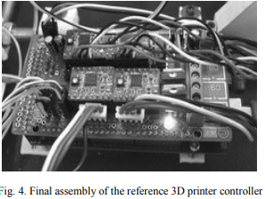
Implementing some of the basic assumptions about the traffic RepRap in the way of universal access to printer components, many projects control system constructions base on a relatively low-cost development boards [7]. The reference model uses the popular Arduino base plate with an 8-bit microcontroller family ATmega and Pololu extension board [8]. The basic and necessary tasks implemented in the controller can be divided into the following categories:
motion/extrusion control,
temperature control,
printer head zero-position detection,
fan/cooling control,
communication with host and/or,
internal memory use for standalone G-Code execution
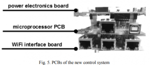
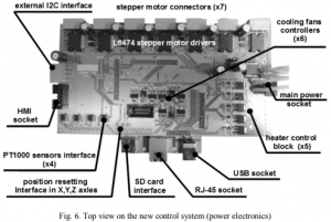
2.2. New control system
The main goal of the new project is elimination of limitations pointed out in previous chapter by:
use of much more efficient microcontroller family STM32F4 [11] with maximum computing power at 210 [MIPS] and hardware floating point operations support,
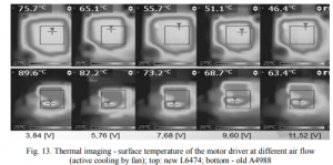
use of L6474 drivers with lower output stage transistors conduction resistance RDS(On) (180/370 [mΩ] with 320/320 [mΩ] in the driver A4988 in low/high side of the output bridge), lower thermal resistance (32 [K/W] reduced to 12 [K/W]), a higher value of effective continuous phase current (3[A] vs 2[A] in reference design),
2.3. Interfaces
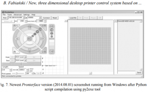
The very important aspect of the new design is to introduce Ethernet interface as an alternative to the USB. The USB interface at FS (full speed) mode uses standard STM32F4 peripheral. Embedded system driver is developed to comply with CDC device class [13]. Furthermore, after taking into account the Windows system requirements [14] it is possible to use standard USB driver with no additional installation requirement.
3. Experimental results
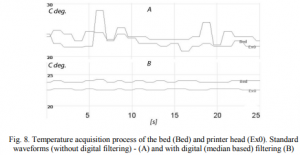
3.1. Temperature measurements The challenge for analog-to-digital converting channels in the controller is running wires transmitting these signals parallel with motor and heater power
cables. Heater current has almost rectangular form with value up to12 [A] and even more in large printers. The values results from the direct measurement of the analog-to-digital converters are subjected to filtration using various algorithms. The implementation effects of one of them shows Figure 8, in comparison with nominal measurement. Digital filter algorithm resulting from Figure 8 (B) bases on the number of M consecutive samples saving in memory
3.2. Motor drives
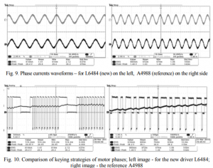
As can be seen from stacked waveforms in Figure 9, motor drives are characterized by similar waveforms of phase currents at the control mode of 1/16 micro stepping. However, differences are visible in the way of keying both units (Figure 10), which difference is externalized in generated noise during operation.
4. Conclusions
The paper presents the design of a new three-dimensional printer control system developed on the basis of experience in the current operation of equipment for the desktop market. 3D printing technology basics and its history were introduced. Solutions that improved operational stability and functionality compared to the original design based on the achievements in the domain of open source software were proposed. Increased control over the printing process was described as the error feedback signal from motor drivers was utilized in the system.
COMMENTS