appropriate operating commands to the HVAC system through analyzing its operational data.[3]The operational
data of HVAC system is not only an important indicator to assess building energy consumption but also works as
the feedback of the control system. Considering that the sensors of the HVAC system usually distribute dispersedly
so the traditional data acquisition system encountered difficulties in cabling, maintenance and readjustment [4] and
usually has a low efficiency and poor accuracy in data transmission [5].
Wireless Data Acquisition system developed in this pa per is based on the Wireless Sensor Network and the
embedded system technology. Wireless Sensor Network is an intelligent measurement and management Network
which is constituted by a large number of tiny sensors distributed in the monitoring areas with the ability of sensing,
computing and communicating [6]. The Wireless Data Acquisition system has the characters of easy installation and
stable and efficiency data transmission, providing a good solution to the cabling problems exist in practical
application and the signal attenuation in transmission process.
2. Description of the development process of the Wireless Data Acquisition system
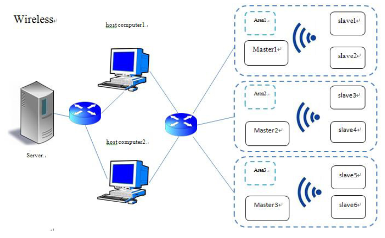
The system is divided into two parts, part on e called slave device is used to collect real -time signal from the
sensors distributed in the HVAC system and send it out. The other part called the master device is used to receive
data sent from the slave devices and store it for the moment then upload the proceeded data to the host computer.
The system is distributed into different collection area according to the actual circumstances around the HVAC
system. Each collection area has one master device and a number of slave devices and the master device and slave
devices are connected into a tree network.
Fig. 1. Architecture of Data Process and Transmission.
After the analog to digital conversion the slave devices send the digital data to the corresponding master device
at a regular time through the wireless module. In different acquisition area each slave device is assigned a digital ID.
When a new slave device join into the acquisition area the master device will assign the slave device a new ID and
arrange a new piece of memory for it. Master device in different area are distinguished by IP address. During the
acquisition process master device keeps receiving data sent from slave devices in each acquisition area and waiting
2008 Hao Yu et al. / Procedia Engineering 121 (2015) 2006 – 2013
for command from the host computer. Whenever receiving the data-transferring command from the host computer,
master device packs the data in specific formation and transfer it to the host computer through the Ethernet module.
The overall architecture of the system is shown in Fig.1.
2.1. Hardware Designation of the Wireless acquisition system
As shown in Fig.2 the Master device consists of a MCU, a wireless module, user button, and an Ethernet
module .the slave device consists of a MCU, acquisition circuit, wireless module, special power module. The master
device and slave device utilize the same MCU and wireless module.
Fig. 2. Hardware designation of master and slave devices.
In this system STM32F103RBT6 works as the MCU, which contains a Cortex-M3 core, 128K FLASH and 16K
SRAM for data storage and application. With 72MHZ maximum operating frequency, STM32F103RBT6 also
contains many kinds of peripheral interface resources, including multiple 12-bit A / D converter, CAN bus interface,
SPI communication interface and multiple serial ports [7].
NRF24L01 is used as the Wireless communication module because of its characteristics as follows: With
2.4GHz opening global ISM band, high transmission power, low voltage, high transfer rate, nRF24L01 supports up
to six channels of data reception and hardware CRC error detection are built in the module. [8]
Master device communicates with the host computer through the W5100 Ethernet module. W5100 chip
integrates a stable TCP / IP protocol stack, an Ethernet media transport layer (MAC) and a physical layer (PHY)
inside itself. The internal hardware in the form of TCP / IP protocol stack of w5100 supports such as TCP, UDP,
IPv4, ARP, IGMP and all these agreements have been utilized in many areas after years of testing. [9] Users do not
need to care much about the control of Ethernet communication protocol layer and W5100 has a simple
programming interface supporting both parallel and SPI serial mode and the interface can be easily connected to the
microcontroller. Hardware connection of the nRF24L01 and W5100 are shown in Fig. 3.
2.2. Software Designation of the Wireless acquisition system
In the acquisition process master device waiting for wireless interrupt and network interrupt.
In the wireless interrupt response function master device process the data received from slave devices. In
network interrupt response function master device analyze the interrupt status and complete corresponding task. The
working process of master device is shown in Fig. 4.
Slave device stays in a loop in which it first keeps in waiting state until sampling time has come then it begins
data acquisition and sending process. The working process of slave device is shown in Fig. 5.
2009Hao Yu et al. / Procedia Engineering 121 (2015) 2006 – 2013
Fig. 3. Hardware circuit of the W5100 and nRF24L01.
Fig. 4. Flow chart of the master device.
2010 Hao Yu et al. / Procedia Engineering 121 (2015) 2006 – 2013
An corresponding acquisition software has also been developed on the host computer to communicate with all
the master device in UDP and aggregate data to the native database. After the UDP communication has been built up,
the software build up two independent thread (sending thread and receiving thread) to work synchronously in the
acquisition process. The work flow chart is shown in Fig. 6.
Fig. 5. Flow chart of the slave device.
2011Hao Yu et al. / Procedia Engineering 121 (2015) 2006 – 2013
Fig. 6. Software workflow of host computer.
3. Results and discussion
Fig.7 shows an experiment of the wireless data Acquisition system based on the water system of an air
conditioning system. There is one temperature sensor installed at the export of each FCU and one pressure sensor
installed between the export and import of each FCU. One pressure sensor and one temperature sensor are installed
at the export and import of the evaporator. The evaporator and the FCU are distributed in three separated rooms.
Despite the presence of high power electrical equipment in the laboratory which has strong electromagnetic
interference to the acquisition system, the system works stably without data loss in a relatively close range (20
meters or less). But when the distance between master and slave devices increases or there are more obstacles
existed between master and slave devices much more serious data loss will occur.
COMMENTS